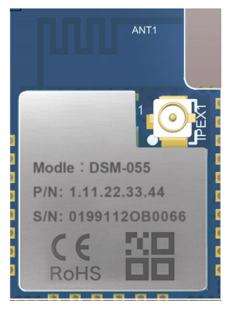
1. Overview of DSM-055 Bluetooth Mesh Module
DSM-055 BLE mesh module employs a 2.4 GHz wireless SOCs optimized for line-powered Bluetooth Low Energy and Bluetooth mesh applications, including connected lighting, smart plugs, gateways and voice
assistants.
An 80 MHz ARM® Cortex®M33 (EFR32BG21A010F768IM32-B) core provides plenty of processing capability while an integrated security subsystem provides leading security features that greatly reduce the risk of IoT security breaches and compromised intellectual property. With better than -104dBm sensitivity and up to +19 dBm output power.
DSM-055 BLE mesh module can support plug-in and patch mode, the production process is simple and convenient, the transmission power is large, and the receiving sensitivity is high, and it can be widely used in the field of smart home, building automation and industrial control.
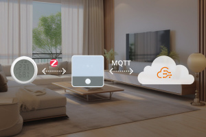
Get to know Bluetooth Grow Light Control via BLE mesh module and Home Assistant
2. Features of DSM-055 Bluetooth Mesh Module
- ARM Cortex-M33, Floating-Point Unit
- Up to 80 MHz Clock Speed
- Up to 1024 KB of Programmable Flash
- Up to 96 KB SRAM
- BLE RF features
Compatible with Bluetooth 5.0 and Bluetooth mesh specification
Excellent receive sensitivity:
-101dBm @125 kbps GFSK
Programmable output power: Up to +19dBm
Active mode RX:8.8mA
Active mode TX:9.3mA@0dBm
Active mode TX: 33.8 mA@10dBm
Antenna: PCB or IPEX - Support master mode, slave mode, broadcast mode (Beacon),
- Support master-slave integration, connecting up to 8 slave devices
- Support multi-master and multi-slave, can connect 3 masters and 4 slaves
- Support SIG mesh, support multiple node types of mesh
- Built-in onboard PCB antenna/reserved IPEX connector for high gain external antenna
- Working temperature: -30℃ to +105℃
- Humidly:<85%RH(No condensation)
3. Applications of DSM-055 Bluetooth Mesh Module
- Intelligent building
- Smart household and home appliances
- Smart socket and light
- Industrial wireless control
- Baby monitor
- Network camera
- Intelligent bus
4. Interfaces of DSM-055 Bluetooth Mesh Module
DSM-055 dimensions are 14.5 (±0.35) mm (W)×20 (±0.35) mm (L) ×2.8(±0.15) mm(H):

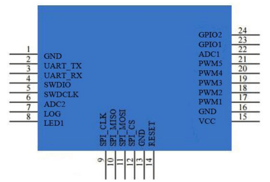
| Pin No. | Symbol | I/O type |
Function |
|---|---|---|---|
| 1 | GND | P | Power supply reference ground pin |
| 2 | UART_TX | PA05 | MP test points need to be reserved for calibration |
| 3 | UART_RX P | PA06 | MP test points need to be reserved for calibration |
| 4 | SWDIO | PA02 | GPIO interface; 8mA drive capability. Wake-up function. Internal strong/weak pull-up and pull-down. SWDIO (default) |
| 5 | SWDCLK | PA01 | |
| 6 | ADC2 | PB02 | GPIO interface, which can be configured as an ADC |
| 7 | LOG | PB01 | Power-on mode: normal operation pull-down, bypassing the program code executed in the flash (the PAD internal pull-down by default). |
| 8 | LED1 | PB00 | Common GPIO interface |
| 9 | SPI_CLK | PC02 | Common GPIO interface |
| 10 | SPI_MISO | PC01 | Common GPIO interface |
| 11 | SPI_MOSI | PC00 | Common GPIO interface |
| 12 | SPI_CSN | PC03 | Common GPIO interface |
| 13 | GND | GND | Power supply reference ground pin |
| 14 | RESET | RESET | MP test points need to be reserved for calibration |
| 15 | VCC | VCC | 1. Power:2V ~ 3.6V 2. MP test points need to be reserved for calibration |
| 16 | GND | P | Power supply reference ground pin |
| 17 | PWM1 | PD04 | Support PWM function LED (fixed timer), default connection cold LED |
| 18 | PWM2 | PD03 | Support PWM function LED (fixed timer), default connection warm LED |
| 19 | PWM3 | PD02 | 1. The I2C SDA 2. LED support PWM such as breathing light (adjustable timer) 3. Red LED by default |
| 20 | PWM4 | PC04 | 1. The I2C SCL 2. LED support PWM such as breathing light (adjustable timer) 3. Green LED by default |
| 21 | PWM5 | PC05 | 1. LED support PWM such as breathing light (adjustable timer) 2. Blue LED by default |
| 22 | ADC1 | PD00 | Common GPIO interface |
| 23 | GPIO1 | PA03 | Common GPIO interface |
| 24 | GPIO2 | PA04 | Common GPIO interface |
Note: P indicates a power supply pin, I/O indicates an input/output pin and AI indicates
an analog input pin. If you have your requirements on the light color controlled by PWM output,
please contact the business representative of Dusun.
5. Electrical Parameters of DSM-055 Bluetooth Mesh Module
| Parameter | Description | Minimum value | Maximum value | Unit |
|---|---|---|---|---|
| Ts | Storage temperature | –30 | 125 | ℃ |
| VCC | Power supply voltage | –0.3 | 3.8 | V |
| Static electricity discharge voltage (human body model) |
TAMB-25℃ | - | 2 | KV |
| Static electricity discharge voltage (machine model) |
TAMB-25℃ | - | 1 | KV |
| Parameter | Description | Minimum value | Typical value | Maximum value | Unit |
|---|---|---|---|---|---|
| Ta | Working temperature | –30 | - | 105 | ℃ |
| VCC | Working voltage | 1.75 | 3.3 | 3.8 | V |
| VIL | I/O low level input | –0.3 | - | VCC*0.3 | V |
| VIH | I/O high level input | VCC*0.7 - | - | VCC | V |
| VOL | I/O low level output | VSS | - | 0.3 | V |
| VOH | I/O high level output | VCC–0.3 | - | VCC | V |
| Symbol | Conditions | Typical value | Unit |
|---|---|---|---|
| Itx | Constantly transmit, output power of 0 dBm | 10.5 | mA |
| Irx | Constantly receive | 9.4 | mA |
6. RF Features of DSM-055 Bluetooth Mesh Module
Unless otherwise indicated, typical conditions are: TA = 25℃, VCC = 3.0V, RF center
frequency 2.45 GHz.
| Parameter | Minimum value | Typical value | Maximum value | Unit |
|---|---|---|---|---|
| Average RF output power | –20 | 0 | 20 | dBm |
Unless otherwise indicated, typical conditions are: TA = 25℃, VCC = 3.0V, RF center
frequency 2.45 GHz.
| Parameter | Minimum value | Typical value | Maximum value | Unit |
|---|---|---|---|---|
| RX sensitivity | 1 Mbps | –95 | –97 | dBm |
| RX sensitivity | 2 Mbps | –93 | –94 | dBm |
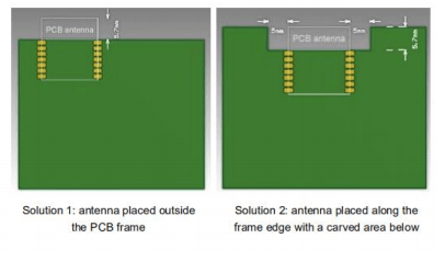
7. Antenna of DSM-055 Bluetooth Mesh Module
DSM-055 uses an onboard PCB antenna or IPEX antenna.
To ensure the optimal RF performance, it is recommended that the antenna be at least
15 mm away from other metal parts.
Because DSM-055 is mounted to the main control panel through SMT, the placement location
and manner of the PCB directly affect the RF performance. The following are placement
positions recommended and not recommended.
Among them, placement positions in Solution 1 and 2 are recommended, that is, the antenna
is placed outside the frame of the panel, or the antenna is placed along the frame edge
of the panel with a carved area below. In the above two solutions, the RF performance is
not different from that of an independent module.
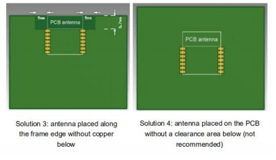
If the PCB antenna must be placed on the panel due to the design limit, you can refer
to the placement manner in Solution 3. That is, the antenna is placed along with the frame
of the panel without copper or traces below. However, the RF performance is still reduced
by 1 to 2 dBm.
The placement position in Solution 4 is not recommended. In this solution, the antenna
is placed on the PCB without a clearance area below, which greatly affects the strength
of the RF signal.
8. Instructions of DSM-055 Bluetooth Mesh Module
Use an SMT placement machine to mount components to the stamp hole module that Dusun produces
within 24 hours after the module is unpacked and the firmware is burned. If not, vacuum pack
the module again. Bake the module before mounting components to the module.
- SMT placement equipment:
Reflow soldering machine
Automated optical inspection (AOI) equipment
Nozzle with a 6 mm to 8 mm diameter - Baking equipment:
Cabinet oven
Anti-static heat-resistant trays
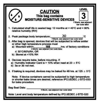
Anti-static heat-resistant gloves - Storage conditions for a delivered module are as follows:
The moisture-proof bag is placed in an environment where the temperature is below 30°C
and the relative humidity is lower than 70%.
The shelf life of a dry-packaged product is six months from the date when the product
is packaged and sealed.
The package contains a humidity indicator card (HIC).

- Bake a module based on HIC status as follows when you unpack the module package:
If the 30%, 40%, and 50% circles are blue, bake the module for 2 consecutive hours.
If the 30% circle is pink, bake the module for 4 consecutive hours.
If the 30% and 40% circles are pink, bake the module for 6 consecutive hours.
If the 30%, 40%, and 50% circles are pink, bake the module for 12 consecutive hours. - Baking settings:
Baking temperature: 125±5℃
Alarm temperature: 130℃
SMT placement ready temperature after natural cooling:<36℃
Number of drying times: 1
Rebaking condition: The module is not soldered within 12 hours after baking. - Do not use SMT to process modules that have been unpacked for more than 3 months, because
electroless nickel/immersion gold (ENIG) is used for PCBs and they are seriously
oxidized for over 3 months. SMT is very likely to cause pseudo and missing soldering.
Dusun is not liable for such problems and consequences. - Before using SMT, take electrostatic discharge (ESD) protective measures.
- To reduce the reflow defect rate, draw 10% of the products for visual inspection and
AOI before the first mounting, to determine the rationality of oven temperature control
and component attachment and placement manners. Draw 5 to 10 modules from subsequent
batches each hour for visual inspection and AOI.
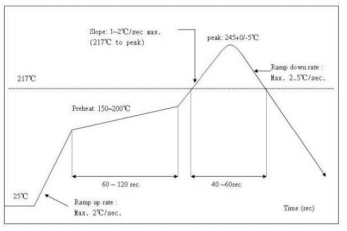
9. Recommended Oven Temperature Curve
Perform SMT based on the following reflow oven temperature curve. The highest temperature
is 245℃. The reflow oven temperature curve is as below:
Refer to IPC/JEDEC standard; Peak Temperature:<245℃; Number of Times: ≤2 times
10. Recommended oven temperature curve and temperature
For oven temperature setting, refer to oven temperatures for wave soldering. The peak
temperature is 260℃±5℃. The wave soldering temperature curve is shown below:
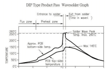
Recommended soldering temperature:
| Recommended wave soldering oven temperature |
Recommended manual soldering temperature |
||
|---|---|---|---|
| Preheat temperature | 80 to 130℃ | Soldering temperature | 360±2℃ |
| Preheat time | 75 to 100s | Soldering time | <3s/point |
| Peak contact time | 3 to 5s | NA | NA |
| Temperature of tin cylinder | 260±5℃ | NA | NA |
| Ramp-up slope | ≤2℃/s | NA | NA |
| Ramp-down slope | ≤6℃/s | NA | NA |
11. Storage Conditions of DSM-055 Bluetooth Mesh Module
12. MOQ and Packaging of DSM-055 Bluetooth Mesh Module
| Product No. | MOQ (pcs) | Shipping packaging method |
Number of modules per reel (pcs) |
Number of reels per carton (reel) |
|---|---|---|---|---|
| DSM-055 | 4000 | Tape reel | 1000 | 4 |