1. Product Description
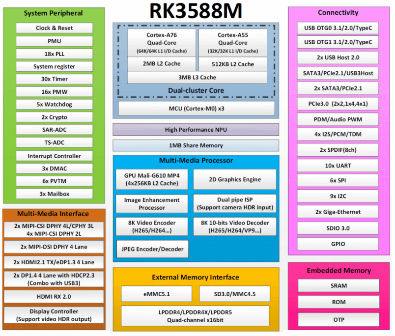
The DSOM-042 System on Module features the RK3588M, a state-of-the-art automotive-grade AI System on a Chip (SoC) designed to deliver low-power, high-performance computing tailored for the automotive industry. Manufactured using an advanced 8nm process, it features an octa-core ARM architecture that combines quad-core Cortex-A76 and Cortex-A55 CPUs, clocked up to 2.4GHz. This powerful core arrangement supports complex tasks required in smart car systems.
For graphics, it integrates a quad-core Mali-G610 GPU, suitable for high-demand in-car entertainment and innovative cockpit interfaces. The SoC’s standout feature is its 6 Tops AI computing power delivered by the Neural Processing Unit (NPU), enabling sophisticated AI applications such as advanced driver-assistance systems (ADAS).
Video capabilities are also robust, with an 8K Video Processing Unit (VPU) and dual 16-megapixel Image Signal Processors (ISPs), allowing for high-resolution video processing vital for both entertainment and driver safety functionalities.
The DSOM-042 3588M System on Module is thus a versatile, powerful chip designed to push the boundaries of automotive technology, enhancing the smart car experience. Besides, the DSOM-042R 3588M System on Module offers a wide range of development documents and software resources that are both free and open-source. This convenience enables developers to enhance their development efficiency and shorten the development cycle.sYS
2. System Block Diagram
3. Basic Parameters and Interfaces
| Item | Parameter |
|---|---|
| CPU | Octa-core 64-bit (4×Cortex-A76+4×Cortex-A55), 8nm advanced process, up to 2.4GHz |
| GPU | ARM Mali-G610 MP4 quad-core GPU supporting OpenGL ES3.2 / OpenCL 2.2 / Vulkan1.1, 450 GFLOPS |
| NPU | NPU algorithm up to 6 TOPS, support INT4/INT8/INT16 hybrid operations, can realize network model conversion based on TensorFlow / MXNet / PyTorch / Caffe and other series of frameworks |
| ISP | Integrated 48MP ISP with HDR&3DNR |
| RAM | 8GB |
| Storage | 128 GB |
| OS | Support for Android 11.0, Ubuntu 18.04 systems |
| Temperature | Operating Temperature: -40°C ~85 °C |
| Storage Temperature: -40°C ~105 °C | |
| Humidity | 10~80%(Non-condensing) |
| Barometric Pressure | 76Kpa ~106Kpa |
| Interface | 1 * BTB Socket (100PIN) + 3 * BTB Socket (80PIN) |
| Thermal Dissipation | Standby power consumption: 1.35W Typical power consumption: 4.8W maximum power consumption: 20W |
| Size | 66mm × 50mm × 5.8mm |
| Ethernet | Integrated PCIe3.0/ GMAC/ SDIO3.0/ USB3.0, expandable multi-gigabit Ethernet, WiFi6 /Bluetooth, 5G/4G LTE |
| Display | Video output: 1 × HDMI2.1 (8K@60fps or 4K@120fps) 1 × HDMI2.0 (4K@60fps) 2 × MIPI-DSI (4K@60fps) 2 × DP1.4 (8K@30fps, multiplexed with USB 3.0) 2 × eDP1.3 (4K@60Hz) 1 × BT.1120 ( 1080@60fps) |
| Camera | HDCP 2.3 1 × MIPI CSI (4 Lane) or 2 × MIPI CSI (2 Lane) 2 × MIPI DC (4-channel DPHY v2.0 or 3-channel CPHY V1.1) 1 × DVP camera interface (up to 150MHz input data) * Support multiple channels 8K video output and 4K video input, up to seven different screens can be realized |
| Audio | 2 × 8-channel I2S 2 × 2-channel I2S 2 × SPDIF 2 × 8-channel PDM (supports multiple MIC arrays) 1 × dual-channel digital audio codec (16-bit DAC) 1 × VAD |
| PCIE | PCIe3.0 (2 × 2lanes, 1 × 4lanes, 4 × 1lanes) 3 × PCIE2.0(1 lanes) |
| SATA | 3 × SATA 3.0 |
| USB | 3 × USB3.0, 4 × USB2.0 Host, 2 × USB2.0 OTG |
| Interface | 9 × I2C, 10 × UART, 5 × SPI, 7 × ADC, 16 × PWM, 1 × SDMMC, GPIO |
4. Pin Definition
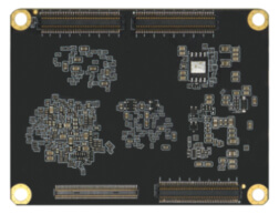
| PIN | ICORE-3588Q Pin Definition | Pad type | IO Pull | Function for Mainboard (MB-Q-RK3588) | Default Function Description | IO Power domain | RK3588 Pin Number |
|---|---|---|---|---|---|---|---|
| 1 | GND | G | GND | GND | GND | ||
| 3 | GND | G | GND | ||||
| 5 | GND | G | GND | ||||
| 7 | GND | G | GND | ||||
| 9 | VCC4V0_SYS | P | VCC4V0_SYS | Core board Power Input:4.0V +/-5% | 4.0V | ||
| 11 | VCC4V0_SYS | P | 4.0V | ||||
| 13 | VCC4V0_SYS | P | 4.0V | ||||
| 15 | VCC4V0_SYS | P | 4.0V | ||||
| 17 | VCC4V0_SYS | P | 4.0V | ||||
| 19 | VCC4V0_SYS | P | 4.0V | ||||
| 21 | VCCA_3V3_S0 | P | VCCA_3V3_S0 | 3.3V Output (Max:300 mA) | 3.3V | ||
| 23 | MIPI_CAMERA0_CLK_M0/ SPDIF1_TX_M1/ I2S1_SDO0_ M0/ PCIE30X1_0_BUTTON_RSTN/ SATA2_ACT_LED_M0/ I2C6_SCL_M3/ UART8_RX_M0/ SPI0_CS1_M1/ GPIO4_B1_u |
I/O | UP | I2S1_SDO_M0_BT | I2S1_SDO_M0_BT | 3.3V | AL24 |
| 25 | BT1120_D15/ SPDIF1_TX_M2/ PCIE20X1_2_PERSTN_M1/ HDMI_TX0_CEC_M0/ I2C8_SDA_M3/ PWM6_M1/ SPI3_CS1_M1/ GPIO4_C1_d |
I/O | DOWN | HDMITX0_CEC_M0 | HDMITX0_CEC_M0 |
3.3V | AK24 |
| 27 | BT1120_D14/ PCIE20X1_2_WAKEN_M1/ HDMI_TX0_SDA_M0/ I2C8_SCL_M3/ SPI3_CS0_M1/ GPIO4_C0_uI |
I/O | UP | HDMITX0_SDA_M0 | HDMITX0_SDA_M0 | 3.3V | AJ25 |
| 29 | BT1120_D13/ PCIE20X1_2_CLKREQN_M1/ HDMI_TX0_SCL_M0/ I2C5_SDA_M1/ SPI3_CLK_M1/ GPIO4_B7_u |
I/O | UP | HDMITX0_SCL_M0 | HDMITX0_SCL_M0 | 3.3V | AJ28 |
| 31 | TYPEC1_USB20_OTG_ID | I | NC | NC | 1.8V | AK8 | |
| 33 | TYPEC1_USB20_VBUSDET | I | NC | NC | 3.3V | AL8 | |
| 35 | TYPEC0_USB20_OTG_ID | I | NC | NC | 1.8V | AL14 | |
| 37 | TYPEC0_USB20_VBUSDET | I | TYPEC0_ USB20_VBUSDET |
TYPEC0_ USB20_VBUSDET, Active H |
3.3V | AM14 | |
| 39 | CIF_D14/ PCIE30X2_CLKREQN_M2/ HDMI_RX_SCL_M1/ I2C7_SCL_M2/ UART9_RTSN_M2/ SPI0_MOSI_M3 |
I/O | DOWN | HDMI_RX_SCL_M1 | HDMI_RX_SCL_M1 | 3.3V | AG25 |
| More | |||||||
5. Product Parameter
| Item | Parameter |
|---|---|
| Exterior | Goldfinger |
| Core Board Size | 66mm*50mm |
| Warpage | less than 0.5 % |
6. The methods of Coreboard Thermal Control
There is a generic thermal system driver framework in the Linux kernel that defines a number of temperature control strategies. The following three strategies are currently in common use:
- Power_allocator: Introduces proportional-integral-derivative (PID) control, dynamically allocates power to each module based on the current temperature, and converts power to frequency to achieve frequency limiting based on temperature.
- Step_wise: Limits the frequency in steps based on the current temperature.
- User space: Does not limit frequency.
The RK3568 chip has a T-sensor that detects the chip’s internal temperature and uses the Power_allocator strategy by default. The operating states are as follows:
- If the temperature exceeds the set temperature value:
– If the temperature trend is rising, the frequency is gradually reduced.
– If the temperature trend is falling, the frequency is gradually increased. - When the temperature falls to the set temperature value:
– If the temperature trend is increasing, the frequency remains unchanged.
– If the temperature trend is falling, the frequency is gradually increased. - If the frequency reaches its maximum and the temperature is still below the set value, the CPU frequency is no longer under thermal control and the CPU frequency becomes system load frequency modulation.
- If the chip is still overheating after the frequency has been reduced (e.g. due to poor heat dissipation) and the temperature exceeds 95 degrees, the software will trigger a restart. If the restart fails due to deadlock or other reasons and the chip exceeds 105 degrees, the otp_out inside the chip will trigger a direct shutdown by the PMIC.
Note: The temperature trend is determined by comparing the previous and current temperatures. If the device temperature is below the threshold, the temperature is sampled every l seconds; if the device temperature exceeds the threshold, the temperature is sampled every 20ms, and the frequency is limited.
The RK3588M SDK provides separate thermal control strategies for the CPU and GPU. Please refer to the (Rockchip_ Developer_ Guide_ Thermal) document for specific configurations.
| Model | RAM | eMMC |
|---|---|---|
| DSOM-042R | 8GB | 128GB |

