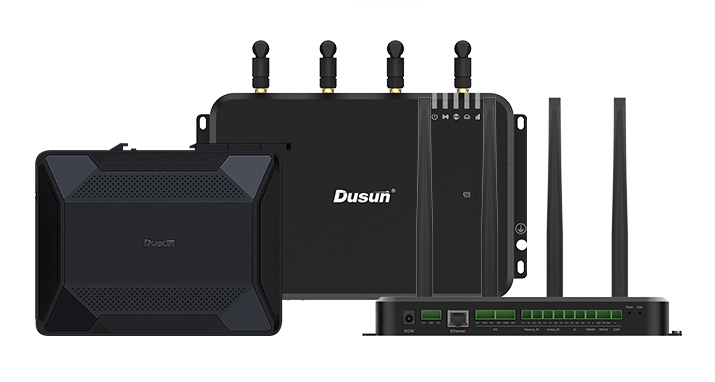
Product Name: DSOM-110R
Product model: RK3568
1. DSOM-110R Rockchip RK3568 SOM Product Description
The DSOM-110R Goldfinger System on Module features Rockchip’s RK3568 64-bit processor, which includes a dual-core GPU and high-performance NPU. Besides, it features Bluetooth 5.2 and Gigabit Ethernet connectivity, up to 4Kp60 video encoding and decoding with H.265 and VP9 codecs, camera interfaces for up to two 8MP cameras or one 16MP camera, and support for operating systems including Android, Linux and Ubuntu. It also supports interfaces such as USB 3.0 and 2.0, HDMI 2.0a for 4K video output, MIPI-DSI and LVDS display interfaces, and I2S and S/PDIF audio interfaces.
With support for up to 8G of RAM, this System on Module is well suited for a range of applications, including smart NVRs, cloud terminals, IoT gateways and industrial control systems.
The DSOM-110R System on Module offers a wide range of development documents and software resources that are both free and open-source. This convenience enables developers to enhance their development efficiency and shorten the development cycle.
- Gold-plated connectors make installation easy. Just plug and play.
- Size 82mm*50.5mm
- eMMC 64GB (32GB/64GB/128GB optional)
- RAM 8GB (2GB/4GB/8GB optional)
- Support for sleep/wake-up function
- Support for Android 11.0, Ubuntu 18.04
- 2-Port Gigabit Ethernet
- Support Wi-Fi6 and 5G/4G expansion
- MXM3.0 314P standard interface, 0.5mm pitch, immersion gold technology, and electroplated hard gold for Gold Finger
- Using RK3568/RK3568B2 as CPU, core module temperature range -20~60 degrees
- RoHS certified
- Stable and reliable product tested for high and low temperature, repeated reboot, Android stability, and AnTuTu benchmark
- Work continuously for 7 days and 7 nights without crashing (or failing).
- Industrial-embedded Linux computer
- Home Appliances
- Home Automation – Smart Home
- Human-machine Interfaces (HMI)
- Point-of-sale (POS) terminals
- Cash Register
- 2D barcode scanners and printers
- Smart grid infrastructure
- IoT gateways
- Residential gateways
- Machine vision equipment
- Robotics
- Fitness/outdoor equipment
2. Basic Parameters and Interfaces of DSOM-110R Rockchip RK3568 SOM
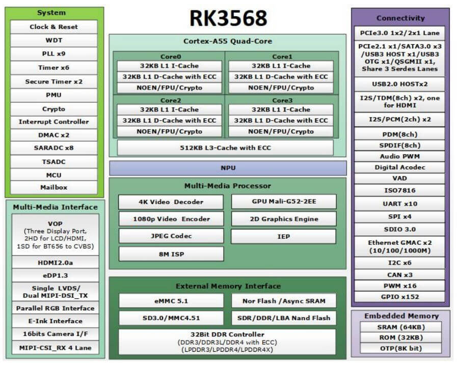
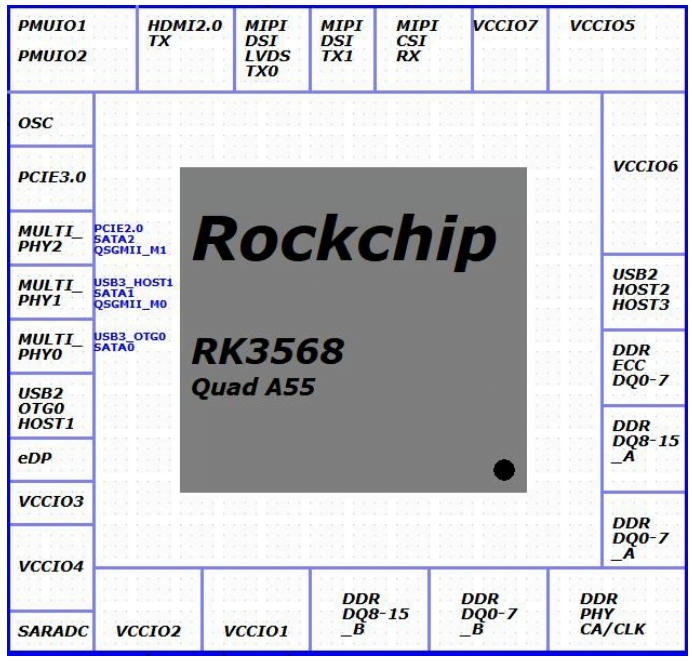
3. Basic Parameters and Interfaces of DSOM-110R Rockchip RK3568 SOM
| Item | Parameter |
|---|---|
| CPU | Quad-core 64-bit Cortex-A55, 22nm lithography process, frequency up to 2.0GHz |
| GPU | ARM G52 2EE Supports OpenGL ES 1.1/2.0/3.2, OpenCL 2.0, Vulkan 1.1 Embedded high-performance 2D acceleration hardware |
| NPU | 0.8Tops@INT8, integrated high-performance AI accelerator RKNN NPU Supports one-click switching of Caffe/TensorFlow/TFLite/ONNX/PyTorch/Keras/Darknet |
| VPU | Supports 4K 60fps H.265/H.264/VP9 video decoding Supports 1080P 60fps H.265/H.264 video encoding Supports 8M ISP, supports HDR |
| RAM | 8GB (2GB/4GB/8GB LPDDR4 optional) |
| Storage | eMMC 64 GB (32GB / 64GB / 128GB eMMC optional) |
| Power Managemennt | RK809-5/RK860 Dynamic adjustment of the output voltage of each DC-DC converter |
| Operating Voltage | Typical voltage 5V/1.5A |
| OS | android/debain |
| Temperature | Operating Temperature: -20 °C ~60 °C |
| Storage Temperature: -20 °C ~70 °C | |
| Humidity | 10~80%(Non-condensing) |
| Barometric Pressure | 76Kpa ~106Kpa |
| Size | 82mm×50.5mm |
| Item | Parameter |
|---|---|
| Ethernet | Integrated GMAC Ethernet controller extended 2×RJ45 (1000Mbps) |
| Wireless | With SDIO port to extend WiFi&Bluetooth two-in-one module -- Supports 2.4G/5GHz Dual-band WiFi, WiFi 6, 802.11 a/b/g/n/ac/ax -- Supports BT5.0 Supports 5G/4G LTE |
| Display | 1 × HDMI2.0, 4K@60fps 2 × MIPI DSI, 1920*1080@60fps (or dual-channel 1×MIPI DSI 2560*1440@60fps) 1 × eDP1.3 , supports 2560x1600@60fps output * Supports up to three screen outputs with different display |
| Camera | 2 × MIPI-CSI (Single-channel 4Lan MIPI CSI or Dual-channel 2Lan MIPI CSI) |
| Audio | 1 × HDMI audio output 1 × Speaker output (1.3W 8Ω) 1 × Earphone output 1 × Microphone onboard audio input |
| PCIE | 1 × PCIe 3.0(2Lane) 1 × PCIe 2.1(1Lane) |
| SATA | 3 × SATA 3.0 |
| USB | 2 X USB 3.0, 2 X USB 2.0 |
| Interface | 3×SDMMC 3×SPI 10×UART 6×I2C 2×I2S/PCM(2ch)/TDM(8ch) 16×PWM 7×ADC 3×CAN 130×GPIO |
| Power | 5V input(±5%) VCC_1V8 output VCC3V3_SD output VCCIO_ACODEC output VCC_3V3 output VCCIO_WL input |
4. Electrical Parameters of DSOM-110R Rockchip RK3568 SOM
| Parameter | Description | Min | Typ | Max | Unit |
|---|---|---|---|---|---|
| VCC5V0_SYS(_1/_2/_3) | VCC5V0_SYS | -0.3 | 6.0 _ | V | |
| VCC_IO_1 VCC_IO_2 |
3.3V IO Output Voltage | -0.3 | 3.6 _ | V | |
| VCC_1V8 | 1.8V IO Output Voltage | 0.7 | 2 | V | |
| Ta | Operating temperature range | -20 | 60 | ℃ | |
| Ts | Store temperature range | -20 | 70 | ℃ |
Note: Exposure to conditions beyond the absolute maximum ratings may cause permanent damage and affect the reliability and safety of the device and its systems. The functional operations cannot be guaranteed beyond specified values in the recommended conditions.
| Parameter | Description | Min | Typ | Max | Unit |
|---|---|---|---|---|---|
| VCC5V0_SYS(_1/_2/_3) | VCC5V0_SYS | 4.8 | 5 | 3.2 | V |
| VCC_IO_1 VCC_IO_2 |
3.3V IO Output Voltage | 3.0 | 3.3 | 3.5 | V |
| VCC_1V8 | 1.8V IO Output Voltage | 1.7 | 1.8 | 1.9 | V |
| VCC5V0_SYS Supply | VCC5V0_SYS Input Current | A | |||
| Ta | Operating temperature range | -20 | 25 | 60 | ℃ |
| Ts | Store temperature range | -19 | 25 | 70 | ℃ |
5. Hardware Design Guidelines of DSOM-110R Rockchip RK3568 SOM
The RK3568 integrates three SDMMC controllers, all of which support the SD V3.01 and MMC V4.51 protocols. Of these, SDMMC0 and SDMMC1 can support up to 200MHz, while SDMMC2 can only support up to 150MHz.
- The SDMMC0 interface is multiplexed in the VCCIO3 power domain.
- It supports system boot and is assigned to the SD card function by default.
- SDMMC0 is multiplexed with JTAG and other functions. Function selection is controlled by SDMMC0_DET status by default. See section 2.1.5 for more details.
- VCCIO3 is the power supply and requires an external 3.3V or 1.8V power supply. If an SD card is connected:If only SD2.0 mode is supported, a 3.3V power supply can be provided directly.If SD3.0 mode is supported in addition to SD2.0 mode, the default power supply is 3.3V. After negotiating with the SD card to run in SD3.0 mode, the power supply needs to be switched to 1.8V. This can be achieved using the RK809-5’s LDO5, which supplies power to VCCIO3 separately. If an SDIO device is connected, 1.8V or 3.3V must be supplied, depending on the peripheral and the actual operating mode.
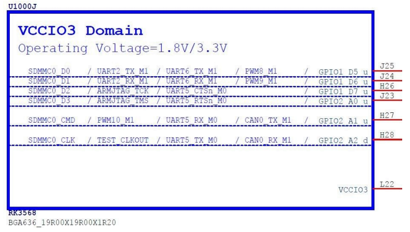
- When making board-to-board connections via connectors, it is recommended to add a certain value of the resistor in series (between 22and 100 ohms, subject to SI testing) and to reserve TVS devices.
- If an SD card is used, the following points must be observed:
- The VDD pin of the SD card should be supplied with 3.3V and the
decoupling capacitors should not be removed. They should be placed
close to the card slot. - The signals SDMMC0_D[3:0], SDMMC0_CMD, and SDMMC0_CLK must
be connected in series with a 22 Ohm resistor, and the signal
SDMMC0_DET must be connected in series with a 100 Ohm resistor. - ESD devices must be placed at the SD card location for the
SDMMC0_D[3:0], SDMMC0_CMD, SDMMC0_CLK, and SDMMC0_DET
signals. If SD3.0 mode is to be supported, the structure capacitance of
the ESD device must be less than 1pF. If only SD2.0 mode needs to be
supported, the ESD device structure capacitance can be relaxed to 9pF.

The recommended pull-up/down and matching design for the SDMMC0 interface are as follows:
| Signal | Internal pull up/down | Connection method | Description |
|---|---|---|---|
| SDMMC0_D[3:0] | Pull-up | Pull-upSeries with 22ohm resistor Use corresponding IO internal pull-up resistor |
SD data transmission/reception |
| SDMMC0_CLK | Pull-down | Series with 22ohm resistor | SD clock transmission |
| SDMMC0_CMD | Pull-up | Pull-upSeries with 22ohm resistor Use corresponding IO internal pull-up resistor |
SD command transmission/reception |
| SDMMC0_DET | Pull-up | Series with 100ohm resistor Use the corresponding IO internal pull-up resistor |
SD card insertion detection |
- The SDMMC1 interface is multiplexed in the VCCIO4 power domain.
- It does not support System Boot and is assigned by default to the SDIO WIFI function.
- VCCIO4 power supply can be 1.8V or 3.3V depending on the peripheral and the actual operating mode. It is important to ensure consistency with the IO of the peripheral. When using SD card function, attention should be paid to the power domain voltage, as with SDMMC0.
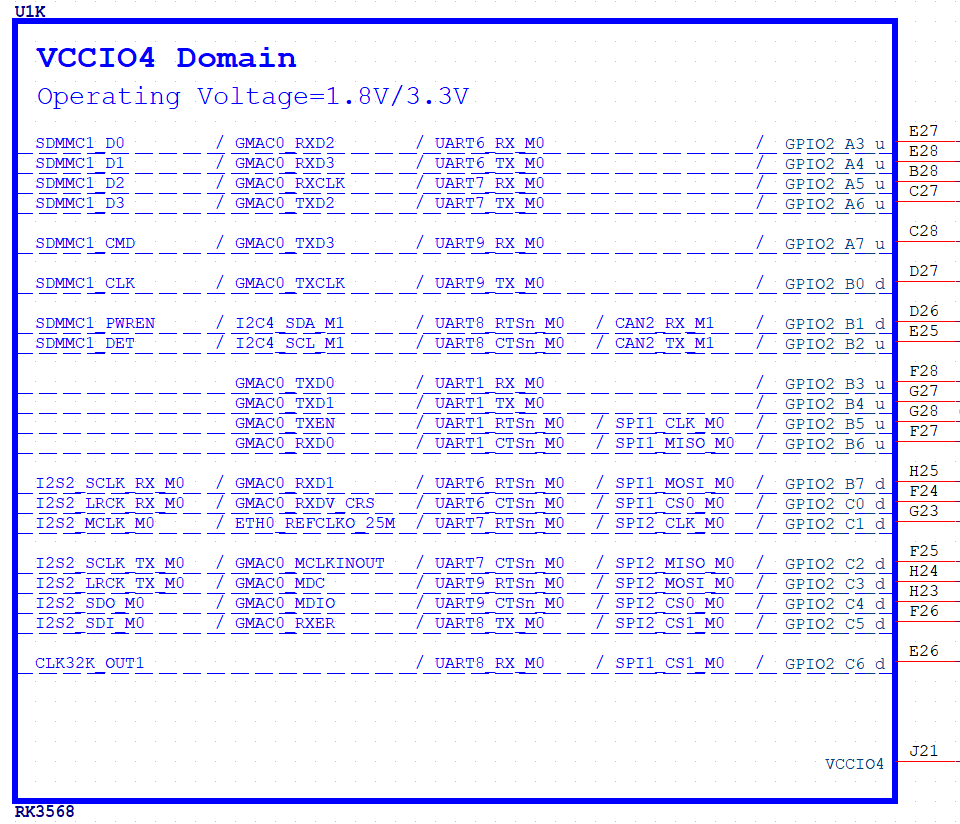
The recommended pull-up/down and matching design for the SDMMC1 interface are as follows:
| Signal | Internal pull up/down | Connection method | Description |
|---|---|---|---|
| SDMMC1_D[3:0] | Pull-up | When the wiring is short, a 22ohm resistor in series can be removed, and the corresponding IO internal pull-up resistor can be used instead | SD data transmission/reception |
| SDMMC1_CLK | Pull-down | Series with 22ohm resistor | SD clock transmission |
| SDMMC1_CMD | Pull-down | When the wiring is short, a 22ohm resistor in series can be removed, and the corresponding IO internal pull-up resistor can be used instead | SD command transmission/reception |
- When connecting to a SDIO WIFI module, low power standby solutions must be considered, including moving the relevant control pins to the PMUIO1/2 power domain. When VDD_LOGIC is off, the IO states in the VCCIO1/2/3/4/5/6/7 power domain cannot be maintained.
- When implementing board-to-board connections via connectors, it is recommended to add a certain value of resistor in series (between 22 Ohm and 100 Ohm, depending on the SI test requirements) and to reserve TVS devices.
- The SDMMC2 interface has two positions that can be multiplexed, one in the VCCIO5 power domain and the other in the VCCIO6 power domain. Only one can be used, either all in the VCCIO5 power domain or all in the VCCIO6 power domain. It is not supported to use VCCIO5 for some and VCCIO6 for others.
- System boot is not supported.
- The supply voltage of VCCIO5 or VCCIO6 can be set to 1.8V or 3.3V depending on the external device and the actual operating mode. It is necessary to ensure consistency with the IO of the external device. When using the SD card function, the power supply voltage should be considered and the requirements are the same as for SDMMC0.
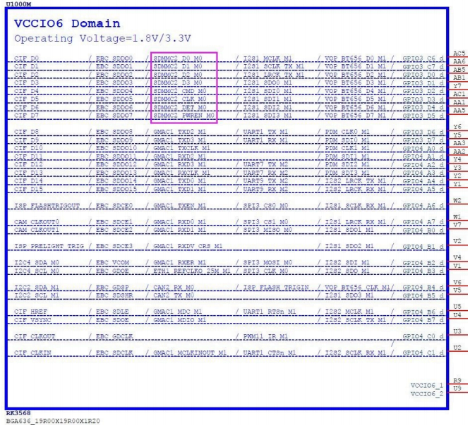
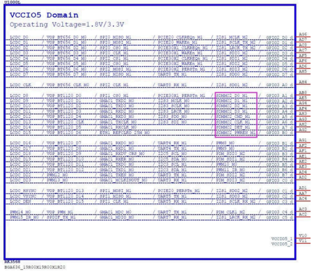
The recommended pull-up/down and matching design for the SDMMC2 interface are as follows:
| Signal | Internal pull up/down | Connection method | Description |
|---|---|---|---|
| SDMMC2_D[3:0] | Pull-up | When the wiring is short, a 22ohm resistor in series can be removed, and the corresponding IO internal pull-up resistor can be used instead | SD data transmission/reception |
| SDMMC2_CLK | Pull-down | Series with 22ohm resistor | SD clock transmission |
| SDMMC2_CMD | Pull-up | When the wiring is short, a 22ohm resistor in series can be removed, and the corresponding IO internal pull-up resistor can be used instead | SD command transmission/reception |
When implementing board-to-board connections via connectors, it is recommended to add a certain value of resistor in series (between 22 Ohm and 100 Ohm, depending on the fulfilment of the SI test requirements) and to reserve TVS devices.
6. Product Dimensions of DSOM-110R Rockchip RK3568 SOM
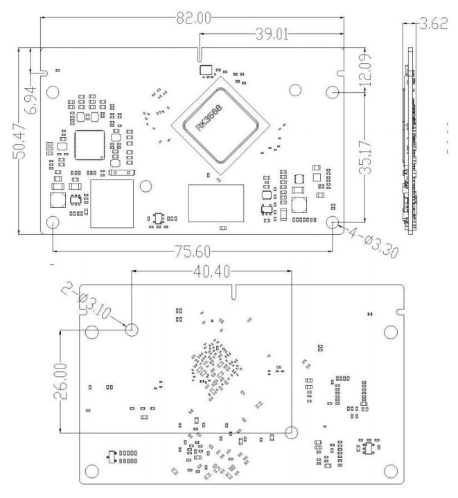
| Item | Parameter |
|---|---|
| Exterior | Goldfinger |
| Core Board Size | 82mm*50.5mm |
| Pin Spacing | 0.5mm |
| Pin Pad Size | 2.7mm*0.35mm |
| Number of Pins | 314 Pins |
| Number of Layers | 8 floors |
| Warpage | less than 0.5 % |
7. The methods of Coreboard Thermal Control
- Power_allocator: Introduces proportional-integral-derivative (PID) control, dynamically allocates power to each module based on the current temperature, and converts power to frequency to achieve frequency limiting based on temperature.
- Step_wise: Limits the frequency in steps based on the current temperature.
- User space: Does not limit frequency.
The RK3568 chip has a T-sensor that detects the chip’s internal temperature and uses the Power_allocator strategy by default. The operating states are as follows:
- If the temperature exceeds the set temperature value:
- If the temperature trend is rising, the frequency is gradually reduced.
- If the temperature trend is falling, the frequency is gradually increased.
- When the temperature falls to the set temperature value:
- If the temperature trend is increasing, the frequency remains unchanged.
- If the temperature trend is falling, the frequency is gradually increased.
- If the frequency reaches its maximum and the temperature is still below the set value, the CPU frequency is no longer under thermal control and the CPU frequency becomes system load frequency modulation.
- If the chip is still overheating after the frequency has been reduced (e.g. due to poor heat dissipation) and the temperature exceeds 95 degrees, the software will trigger a restart. If the restart fails due to deadlock or other reasons and the chip exceeds 105 degrees, the otp_out inside the chip will trigger a direct shutdown by the PMIC.
Note: The temperature trend is determined by comparing the previous and current temperatures. If the device temperature is below the threshold, the temperature is sampled every l seconds; if the device temperature exceeds the threshold, the temperature is sampled every 20ms, and the frequency is limited.
The RK3568 SDK provides separate thermal control strategies for the CPU and GPU. Please refer to the (Rockchip_Developer_Guide_Thermal) document for specific configurations.
8. Production Guide of DSOM-110R Rockchip RK3568 SOM
Select modules that can be SMT or in-line packaged according to the customer’s PCB design scheme. If the board is designed for SMT packaging, use SMT-packaged modules. If the board is designed for in-line assembly, use in-line assembly. Modules must be soldered within 24 hours of unpacking. If not, place them in a dry cabinet with a relative humidity of no more than 10% or re-pack them in a vacuum and record the exposure time (total exposure time must not exceed 168 hours).
Instruments or equipment required for SMT assembly:
- SMT Mounter
- SPI
- Reflow soldering
- Oven temperature tester
- AOI
Instruments or equipment required for baking:
- Cabinet ovens
- Antistatic high-temperature trays
- Antistatic and high-temperature gloves
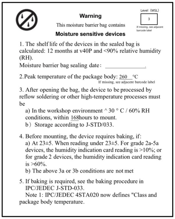
Moisture-proof bags must be stored at a temperature <40°C and humidity <90% RH. Dry-packed products have a shelf life of 12 months from the date of sealing of the package. Sealed packaging with humidity indicator card.

The vacuum bag is found to be broken before unpacking.
After unpacking, the bag is found to be without a humidity indicator card.
The humidity indicator card reads 10% or more after unpacking, and the color ring turns pink.
Total exposure time after unpacking exceeds 168 hours.
More than 12 months from the date of the first sealed packaging.
Baking parameters are as follows:
Baking temperature: 60°C for reel packs, humidity less than or equal to 5% RH; 125°C for tray packs, humidity less than or equal to 5% RH (high-temperature-resistant trays, not blister packs for tow trays).
Baking time: 48 hours for reel packaging; 12 hours for pallet packaging.
Alarm temperature setting: 65°C for reel packs; 135°C for pallet packs.
After cooling to below 36°C under natural conditions, production can be carried out.
If the exposure time after baking is greater than 168 hours and not used up, bake again.
If the exposure time is more than 168 hours without baking, it is not recommended to use the reflow soldering process to solder this batch of modules. The modules are class 3 moisture-sensitive devices and may become damp when the exposure time is exceeded. This may lead to device failure or poor soldering when high-temperature soldering is carried out.
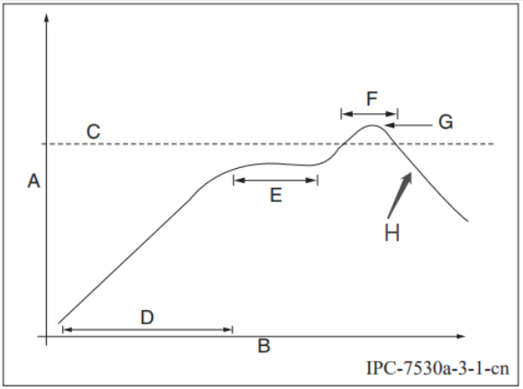
Description for graphs of curves.
A: Temperature axis
B: Time axis
C: Alloy liquid phase line temperature: 217-220°C
D: Slope of temperature rise: 1-3°C/s
E: Constant temperature time: 60-120s, constant temperature: 150-200°C
F: Time above liquid phase line: 50-70s
G: Peak temperature: 235-245°C
H: slope of temperature reduction: 1-4°C/s
Note: The above recommended curves are based on SAC305 alloy solder paste as an example. Please set the recommended oven temperature curve for other alloy solder pastes according to the solder paste specification.
| Model | RAM | eMMC |
|---|---|---|
| DSOM-110R-1 | 2GB | 32GB |
| DSOM-110R-2 | 4GB | 64GB |
| DSOM-110R-3 | 8GB | 128GB |
Documentations
DusunIoT offers full set of development resources including QUICK START, SDK, Firmware packaging, module firmware, Tools, vairous third party software,etc.

