


Heterogeneous multi-core systems usually use shared memory-based communication because the cores must interact and exchange data as they run different functions and operating systems.
There are several custom implementations of this shared memory stack, and these can limit interconnectivity. So we’ll look at the standard memory-sharing layered architecture for heterogeneous AMP systems based on existing components, such as RPMsg and VirtIO. Here’s how it works.
Communication Stack
This communication stack can be split into three OSI protocol layers: physical, Media Access (MAC), and transport layers.

Each of these layers can be implemented separately to allow multiple implementations of one layer, such as RPMsg in the transport layer, to share one implementation of the MAC layer (VirtIO).
Physical Layer
This layer houses the actual hardware needed in this communication stack, which includes the shared memory to be accessed by both cores and the inter-core interrupts. These interrupts are set to a specific configuration, with the minimum one requiring a single interrupt line per core, so two in total at the least.

The RockChip RK3588 SoC series relies on such a setup in its physical layer because it uses a Mailbox hardware module for inter-core communication. This Mailbox transmits interrupt signals between the different cores, which is almost similar to the passing of synchronization semaphores in other systems. But it has some differences, which we’ll look at later.
Some chips, such as those in the NXP family, rely on semaphores for inter-core synchronization, while others rely on hardware elements like inter-core queues and inter-core mutexes.
This synchronization is not necessary when using virtqueue in the Media Access layer.
Media Access Layer (VirtIO/Virtqueue)
This layer eliminates the need for inter-core synchronization because it introduces virtqueue, a single-writer single-reader circular buffering data structure. This data structure enables multiple asynchronous cores to interchange data using Vrings.
Virtqueue is part of the VirtIO architecture, and it helps drivers and devices perform Vring operations. On the other hand, Vring is the current memory layout of a virtqueue implementation.
In Linux distributions, virtqueues are implemented as Vrings, which are ring buffer structures. Each one consists of a descriptor table (buffer descriptor pool), available ring, and used ring.

The Vring structure in the shared memory
These three are physically stored in the shared memory.
Buffer Descriptor
The buffer descriptor has a 64-bit buffer address that stores the address to the buffer held in the shared memory. Each descriptor also has a 32-bit variable buffer length, a 16-bit flag field, and a 16-bit link that points to the next buffer descriptor.

Available Ring Buffer
This input ring buffer has its separate 16-bit flag field, but only the 0th bit in this sector is used. By default, this bit is not set. But if set, the writer side should not get a notification when the reading side consumes a buffer from this input/available ring buffer.
If the bit is left in its default state (not set), This notification is received in the form of the interrupt that we looked at in the physical layer.

The other input field in this available buffer is the head index. Once a buffer index containing a new message gets written in the ring[x] field, the writer updates this head index.
Used Ring Buffer
The last Vring component is the free/used ring buffer, and it has flag and head index fields, just like the available ring buffer. Flags mainly inform the writers whether they should interrupt the other core when updating the head index. Therefore, only the 0th bit in this sector is used. And if set, the writing core won’t get a notification (interrupt) when the reader updates the head index. It operates similarly to the available ring buffer flag field.

However, the buffer has some differences compared to the available ring buffer, and one of them is storing the buffer length for each entry.
But it is important to note that this Vring technique only works on heterogeneous multi-core systems with core-to-core configurations, not core-to-multicore. In core-to-multicore systems, the setup will have multiple writers to the available ring buffer, which would require a synchronization element, such as a semaphore.
Transport Layer (RPMsg)
The RPMsg protocol forms the transport layer in this communication stack. Each RPMsg message is contained in a buffer in the shared memory. This buffer is pointed to by the address field of the buffer descriptor in the Vring pool we looked at in the Media Access layer.
In this buffer, the first 16 bits are used internally by the transport layer, so you won’t find them in the layout.

The 32-bit source address contains the sender’s address or source endpoint, while the destination address has the source endpoint. Next in the RPMsg layout is the 32-bit reserved field, which provides alignment. Since it does not carry any data, it can be used by the transport layer to implement RPMsg (16 bits), leaving 16 bits for alignment.
The last two sections of the RPMsg header are the payload length field (16-bit) and flags field, also 16 bits.
It is uncommon to have an alignment greater than 16 bits in a shared memory heterogeneous multi-core system, but special care should be given if it exceeds this capacity if you’ve allocated part of the space to the transport layer to implement RPMsg.
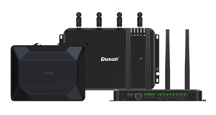
Recommended Heterogeneous Multi-core System on Module
Heterogeneous multi-core systems have become quite popular in embedded high-performance computing applications, such as AI, because they provide a potent mix of performance and power efficiency.
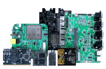
I recommend the DSOM-040R RK3588 system-on-module for such tasks because it is developed on the RK3588 SoC, meaning it has four A76 cores and A55 cores. As stated earlier, these cores use the Mailbox hardware module for inter-core communication.

Although this communication is somehow similar to the semaphores, it relies on interrupts instead. Interrupts can increase CPU efficiency, decrease waiting time, and allow the cores to handle multitasking better.
It is also important to note that the RPMsg buffer is located in the DDR SDRAM by default in these asymmetric heterogeneous multi-core systems.
In the RK3588 SoM series, the internal SRAM is designated for the MPP module. If the system is not utilizing the MPP, you can allocate this SRAM to the RPMsg buffer to enhance performance.
Besides the 64-bit 8-core brains, this module features an ARM Mali-G610 MC4 quad-core GPU that delivers 450 GFLOPS and a high-performance NPU that delivers up to 6 TOPS. It also has a microcontroller unit for low-power control.
Conclusion
In a nutshell, the process of multiple cores trying to access shared memory in a heterogeneous system is akin to different users trying to access data from a shared database. Therefore, there must be a defined way to access the memory with optimized processes to maximize efficiency.
The communication stack explained above is a standardized, efficient architecture that relies on the RPMsg protocol, VirtIO, and core interrupts to use the shared memory in a heterogeneous AMP system. And the RK3588-based DSOM-040R system on module relies on this stack, making it an efficient AMP system architecture that is ideal for handling high-power computational needs while being quick and efficient.
That’s it for this article, and I hope it has been insightful. Please like and share it with your embedded and IoT developer colleagues, and comment below if you need further clarification.
For further custom development services and user case applications, welcome to contact Dusun IoT. We are committed to providing professional services to ensure your product’s successful market launch and foster a prosperous future together!