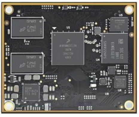
1. Overview of DSOM-070N NXP I.MX 8M Mini SoM
1.1. Product Description
The DSOM-070N I.MX 8M Mini System on Module is developed based on NXP’s multicore embedded applications processor, featuring a quad-core ARM Cortex-A53 that operates at up to 1.8GHz and a 400MHz Cortex-M4 processor. It employs sophisticated 14LPC FinFET process technology to deliver superior speed and improved power efficiency.
The standard memory and storage configuration consists of 2GB DDR4, 8GB eMMC, and 32MB QSPI flash. Optional configuration for RAM and eMMC avaliable.
DSOM-070N I.MX 8M Mini SoM incorporates GigE PHY and PMIC. Various peripherals and I/O signals can be accessed via two 0.8mm pitch 100-pin board-to-board expansion connectors.
DSOM-070N I.MX 8M Mini system on module is compatible with Linux and Android OS. It is designed to provide an accessible and efficient development experience for developers by offering a wide array of free and open-source resources, aiming to make product development more convenient, efficient, and less risky.
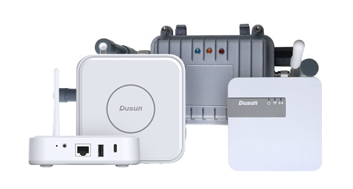
DSOM-070N NXP I.MX 8M Mini System on Module (SOM) is compact in size, measuring only 60mm * 49mm. It is a cost-effective NXP SoM used for developing IoT edge computing, industrial real-time control, industrial data acquisition and control, and IoT predictive maintenance.
1.2. Features
- NXP i.MX 8M mini quad application processor based on 1.8GHz Arm Cortex-A53 and 400MHz Cortex-M4 cores
- 2GB DDR4, 8GB eMMC Flash, 32MB QSPI Flash
- On-board Gigabit Ethernet PHY
- ROHM Power Management IC (PMIC)
- Two 0.8mm pitch 100-pin board-to-board expansion connectors
- Supports operating temperature from -40°C to 85°C
- Supports running Yocto Linux, Ubuntu Linux, Android
1.3. Application
- Industrial Automation
- IoT Devices
- Automotive Infotainment Systems
- Medical Devices
- Consumer Electronics
- Edge AI and Machine Learning
- Audio and Voice Processing
- Security and Surveillance
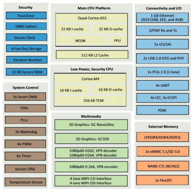
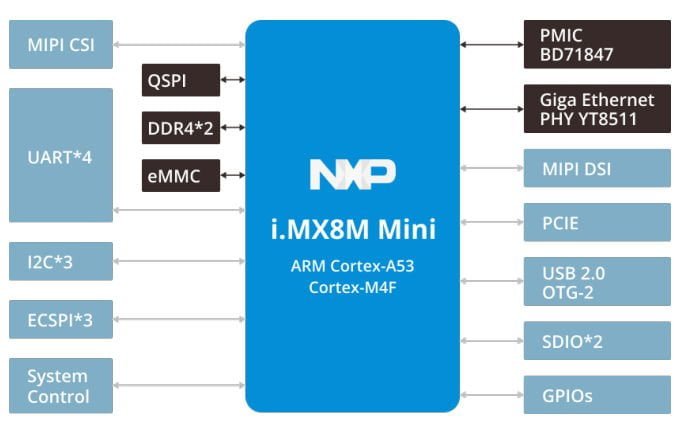
2. System Block Diagram of DSOM-070N NXP I.MX 8M Mini SoM
2.1. Main Chip Block Diagram
2.2. System on Module Block Diagram
3. Basic Parameters and Interfaces of DSOM-070N NXP I.MX 8M Mini SoM
| Item | Parameter |
|---|---|
| Processor | NXP i.MX 8M Mini Processor ●Up to 1.8 GHz Quad-core ARM Cortex-A53 CPU ●400MHz Real-time ARM Cortex-M4 co-processor ●Integrated 2D/3D GPU and 1080p VPU |
| RAM | 2GB DDR4 (supports up to 4GB) |
| Memory | 8GB eMMC Flash (supports up to 64GB) 32MB QSPI Flash |
| Power Input | 5V/ 0.23A |
| OS | Yocto Linux 5.4.3, Ubuntu 18.04, Android 9 |
| Temperature | Operating Temperature: -40 °C ~85 °C (industrial grade) |
| Storage Temperature: -50 °C ~95 °C | |
| Humidity | 10~95%(Non-condensing) |
| Barometric Pressure | 76Kpa ~106Kpa |
| Size | 60mm×49mm |
| PCB | 8 layers, immersion gold process |
| Peripheral | Description |
|---|---|
| Ethernet | 1 x 10/100/1000Mbps Ethernet |
| MIPI DSI | One interface with 4 lanes |
| MIPI CSI | One interface with 4 lanes |
| UART | 4 channels (maximum) |
| USB OTG | 2 channels |
| I2C | 4 channels (maximum) |
| SPI | 3 channels (maximum) |
| GPIO | Up to 103 |
| PCIe | 1 x PCIe |
| PWM | 4 x PWM |
| USB | 2 X USB 2.0 |
4. Pin Definition of DSOM-070N NXP I.MX 8M Mini SoM

| Ref J1 | |||||||
|---|---|---|---|---|---|---|---|
| Pin | Signal Name | Default Function |
Default Function Description |
Level (V) |
I/O | MPU Pin |
Remark |
| 1 | VDD_5V | POWER | 5.0V Power | 5V | Input | ||
| 2 | VDD_5V | POWER | 5.0V Power | 5V | Input | ||
| 3 | VDD_5V | POWER | 5.0V Power | 5V | Input | ||
| 4 | VDD_5V | POWER | 5.0V Power | 5V | Input | ||
| 5 | VDD_5V | POWER | 5.0V Power | 5V | Input | ||
| 6 | VDD_5V | POWER | 5.0V Power | 5V | Input | ||
| 7 | VDD_5V | POWER | 5.0V Power | 5V | Input | ||
| 8 | VDD_5V | POWER | 5.0V Power | 5V | Input | ||
| 9 | DGND | DGND | GND | 0V | |||
| 10 | DGND | DGND | GND | 0V | |||
| 11 | DGND | DGND | GND | 0V | |||
| 12 | DGND | DGND | GND | 0V | |||
| 13 | DGND | DGND | GND | 0V | |||
| 14 | DGND | DGND | GND | 0V | |||
| 15 | DGND | DGND | GND | 0V | |||
| 16 | DGND | DGND | GND | 0V | |||
| ... | |||||||
5. Electrical Parameters of DSOM-070N NXP I.MX 8M Mini SoM
5.1. Main Power Supply(VDD_5V)
The main power supply for the DSOM-070N System on Module is VDD_5V, which corresponds to pins 1 to 10 of the J2 connector. To ensure proper operation, the carrier board must provide a voltage of 5V±5% and ensure that the output capability of the power supply circuit can meet the power consumption of the System on Module. This section lists the power consumption and current of the core board under various conditions. Please reserve an appropriate margin when designing the power supply circuit.
5.2. Power Domain
The external power supply voltage requires the baseboard to provide the corresponding voltage, while the internal generated voltage is produced by the core board itself, without the need for additional power supply.
The System on Module uses VDD_5V for power supply, and the PMIC (Power Management Integrated Circuit) generates multiple different voltages to meet the power supply requirements of modules such as MPU, DDR4, Flash, etc.
| Power | Description | Recommended Voltage Value |
|---|---|---|
| VDD_5V | Main supply voltage, 5V input | 5V |
| VDD_3V33 | 3.33V Output | - |
| VDD_1V8 | 1.8V Output | - |
| USB1_VBUS USB2_VBUS |
USB Power,5V Input | 5V |
| NVCC_SD2 | Support 1.8V/3.3V Output, Software Controllable | 3.3V/1.8V |
Table 5.1 External input/output voltage
| Power | Description | Voltage Value |
|---|---|---|
| NVCC_3V3 | NVCC_SAI1, NVCC_SAI3, NVCC_SAI5, NVCC_ECSPI, NVCC_SD1, NVCC_CLK | 3.3V @3A |
| VDD_SOC_0V8 P | Power supply for SOC | 0.8V@1A |
| VDD_ARM_0V9 VDD_DRAM VDD_VPU_0V9 |
Power supply for ARM core | 0.9V@3A |
| NVCC_DRAM_1V2 | Power supply for DRAM | 1.2V@3A |
| VDD_1V8 | NVCC_JTAG, NVCC_NAND, NVCC_SAI2, NVCC_GPIO1, NVCC_I2C, NVCC_UART | [email protected] |
Table 5.2 Internal generated voltage
5.3. Power Consumption
| Operation Condition | Voltage(V) | Avg Current (mA) | Peak Current(mA) | Total Power(mW) |
|---|---|---|---|---|
| During boot | 5 | 110 | 130 | 550 |
| Full-load stage | 5 | 420 | - | 2100 |
| mem low-power mode | 5 | 10 | - | 50 |
| freeze low-power mode | 5 | 90 | - | 450 |
Table 5.3 Power Consumption Parameter
5.4. GPIO DC Characteristics
| Parameter | Symbol | MIN | TYP | MAX | Unit |
|---|---|---|---|---|---|
| High-level output voltage | VOH (1.8V) | 1.35 | - | - | V |
| VOH (3.3V) | 2.4 | - | - | V | |
| Low-level output voltage | VOH (1.8V) | - | - | 0.36 | V |
| VOH (3.3V) | - | - | 0.4 | V | |
| High-level Input voltage | VOH (1.8V) | 1.26 | - | 1.8 | V |
| VOH (3.3V) | 2 | - | 3.3 | V | |
| Low-level Input voltage | VOH (1.8V) | 0 | - | 0.36 | V |
| VOH (3.3V) | 0 | - | 0.8 | V |
Table 5.4 GPIO DC Characteristics Parameter
Note: Exposure to conditions beyond the absolute maximum ratings may cause permanent damage and affect the reliability and safety of the device and its systems. The functional operations cannot be guaranteed beyond specified values in the recommended conditions.
6. Dimensions of DSOM-070N NXP I.MX 8M Mini SoM
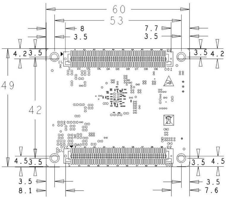
| Item | Parameter |
|---|---|
| Exterior | Board-to-Board Expansion Connectors |
| Core Board Size | 60mm*49mm |
| Number of Pins | 100 Pins |
| Number of Layers | 8 floors |
| Warpage | less than 0.5 % |
7. Production Guide of DSOM-070N NXP I.MX 8M Mini SoM
7.1. SMT process
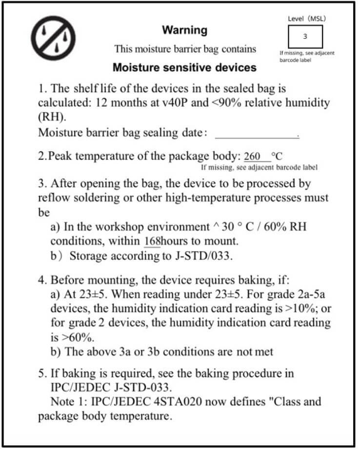
Select modules that can be SMT or in-line packaged according to the customer’s PCB design scheme. If the board is designed for SMT packaging, use SMT-packaged modules. If the board is designed for in-line assembly, use in-line assembly. Modules must be soldered within 24 hours of unpacking. If not, place them in a dry cabinet with a relative humidity of no more than 10% or repack them in a vacuum and record the exposure time (total exposure time must not exceed 168 hours).
Instruments or equipment required for SMT assembly:
- SMT Mounter
- SPI
- Reflow soldering
- Oven temperature tester
- AOI
Instruments or equipment required for baking:
- Cabinet ovens
- Antistatic high-temperature trays
- Antistatic and high-temperature gloves
7.2. Module storage conditions:
Moisture-proof bags must be stored at a temperature <40°C and humidity <90% RH. Dry-packed products have a shelf life of 12 months from the date of sealing of the package. Sealed packaging with humidity indicator card.

7.3. Baking is required when:
The vacuum bag is found to be broken before unpacking.
After unpacking, the bag is found to be without a humidity indicator card.
The humidity indicator card reads 10% or more after unpacking, and the color ring turns pink. Total exposure time after unpacking exceeds 168 hours.
More than 12 months from the date of the first sealed packaging.
Baking parameters are as follows:
Baking temperature: 60°C for reel packs, humidity less than or equal to 5% RH; 125°C for tray packs, humidity less than or equal to 5% RH (high-temperature-resistant trays, not blister packs for tow trays).
Baking time: 48 hours for reel packaging; 12 hours for pallet packaging.
Alarm temperature setting: 65°C for reel packs; 135°C for pallet packs.
After cooling to below 36°C under natural conditions, production can be carried out.
If the exposure time after baking is greater than 168 hours and not used up, bake again.
If the exposure time is more than 168 hours without baking, it is not recommended to use the reflow soldering process to solder this batch of modules. The modules are class 3 moisture-sensitive devices and may become damp when the exposure time is exceeded. This may lead to device failure or poor soldering when high-temperature soldering is carried out.
7.4. ESD
Please protect the module from electrostatic discharge (ESD) during the entire production process.
7.5. Conformity
To ensure product qualification rates, it is recommended to use SPI and AOI test equipment to monitor solder paste printing and placement quality
7.6. Recommended Furnace Temperature Profile
Please follow the reflow profile for SMT placement with a peak temperature of 245°C. The reflow temperature profile is shown below using the SAC305 alloy solder paste as an example.
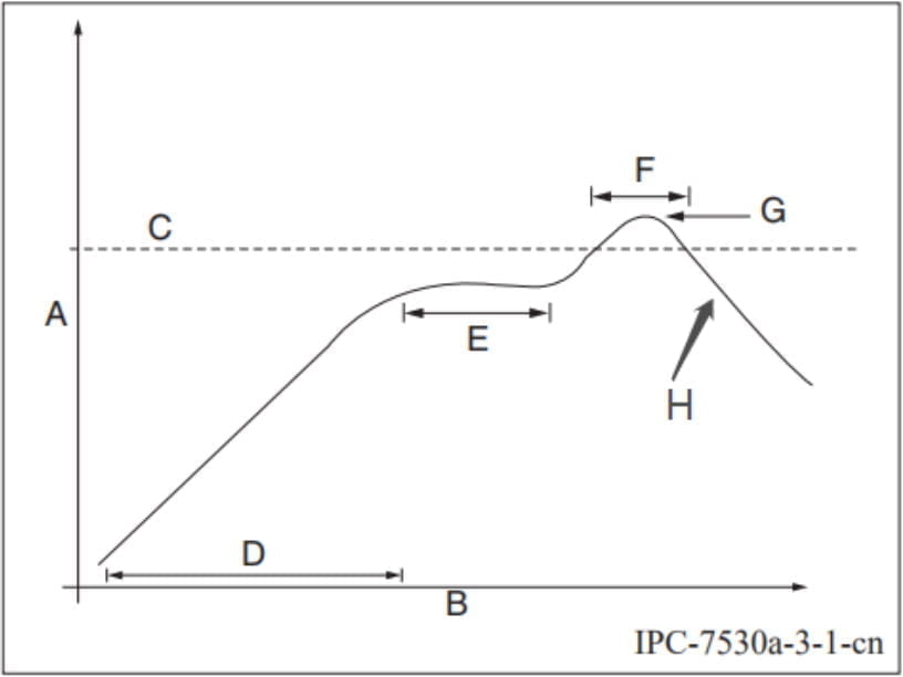
Description for graphs of curves.
A: Temperature axis
B: Time axis
C: Alloy liquid phase line temperature: 217-220°C
D: Slope of temperature rise: 1-3°C/s
E: Constant temperature time: 60-120s, constant temperature: 150-200°C
F: Time above liquid phase line: 50-70s
G: Peak temperature: 235-245°C
H: slope of temperature reduction: 1-4°C/s
Note: The above recommended curves are based on SAC305 alloy solder paste as an example. Please set the recommended oven temperature curve for other alloy solder pastes according to the solder paste specification.
7.7. Storage
7.8. Order Information
DSOM-070N
Configuration: RAM 2GB, eMMC 8 GB.
7.9. Package
TBD