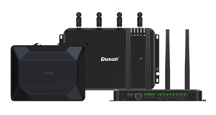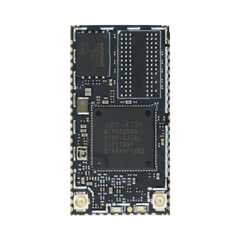
1 Product Description of DSOM-080M MediaTek MT7628 SOM
The DSOM-080M System on Module, produced by Dusun Electronics, is a low-cost and low-power 300M IoT module based on MediaTek MT7628AN as the core. This module provides access to all the interfaces of MT7628AN, supports Linux and OpenWrt operating systems, and allows for custom development. With its rich interfaces and powerful processors, it can be widely used in smart devices or cloud service applications.
The DSOM-080M System on Module offers a wide range of development documents and software resources that are both free and open-source. This convenience enables developers to enhance their development efficiency and shorten the development cycle.
- Super data processing capability, with an MCU main frequency of up to 580MHz
- 300M wireless rate
- Support for 802.11b/g/n mode
- 20/40 channel bandwidth
- Support for AP, STA, and AP/STA mixed mode
- Support for up to 5 10/100M adaptive network ports
- Multiple interfaces: SPI/SD-XC/eMMC
- Rich peripheral interfaces: SPI, I2C, I2S, PCM, UART, JTAG, GPIO
- Widely used in the Internet of Things
- Built-in powerful PMU
- Built-in 64MB DDR2 (MTK7628DAN)
- Support for 16 Multiple BSSID
- Support for multiple encryption methods: WEP64/128, TKIP, AES, WPA, WPA2, WAPI
- Support for QoS, WMM, WMM-PS
- Support for multiple systems: Linux 2.6.36 SDK, OpenWrt 3.10
- Working temperature: -20 to +55℃
- CE, FCC, SRRC certification
- Industrial-embedded Linux computer
- Home Appliances
- Home Automation – Smart Home
- IoT gateways
2 System Block Diagram of DSOM-080M MediaTek MT7628 SOM
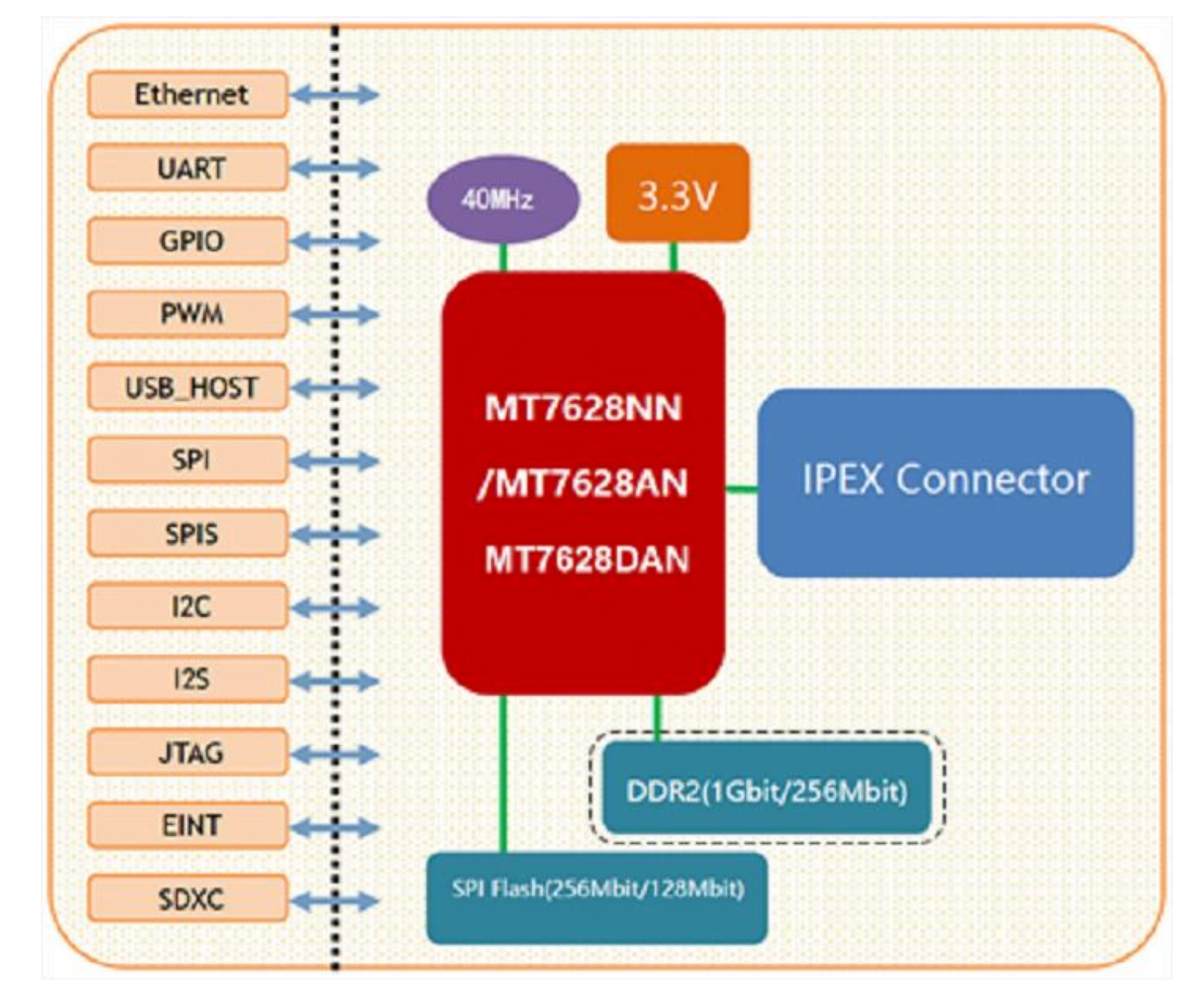
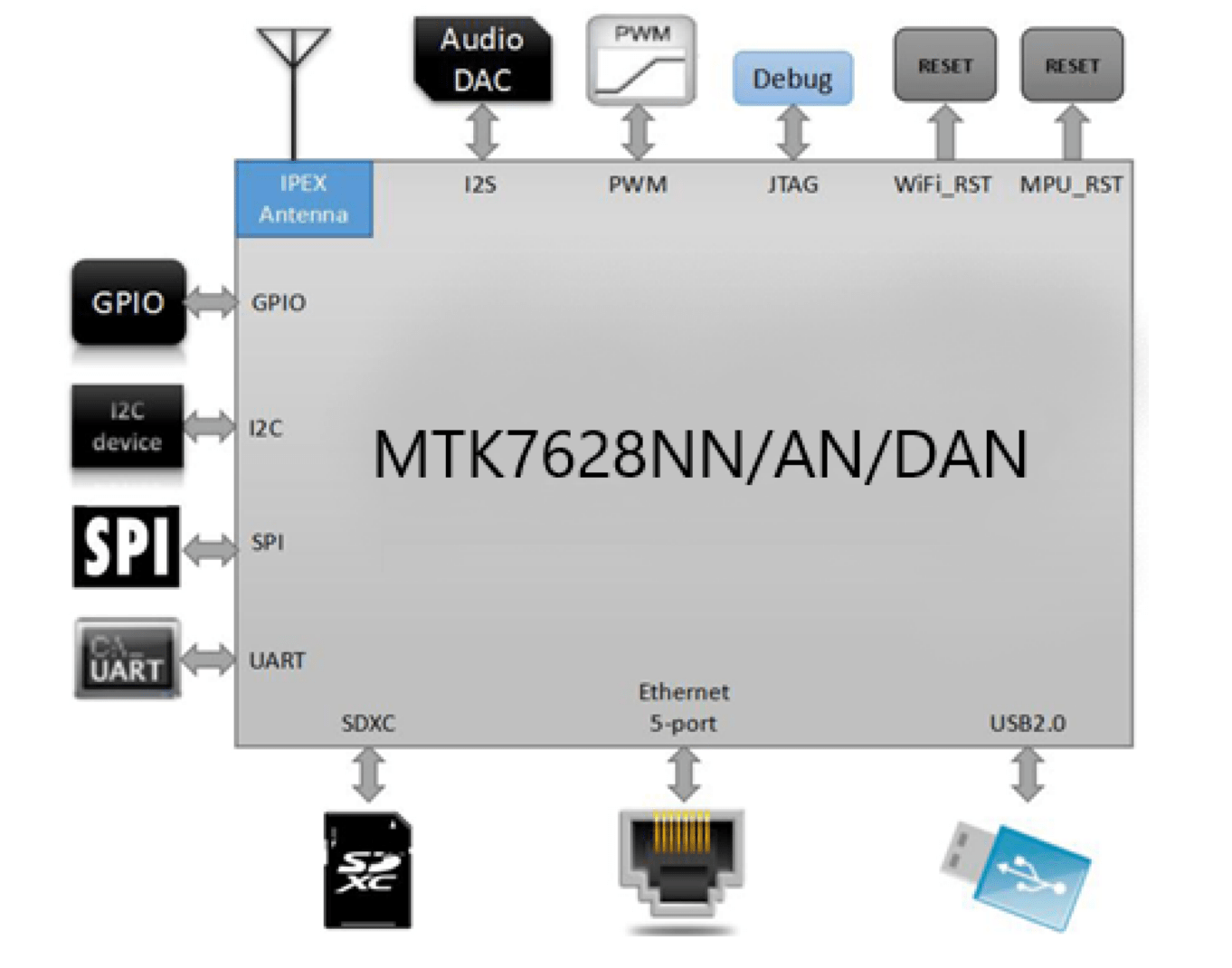
Interface diagram
3 Basic Parameters and Interfaces of DSOM-080M MediaTek MT7628 SOM
| Item | Parameter |
|---|---|
| Mode | DSOM-080M |
| Man chip | MT7628AN |
| Kernel | MIPS24KEc |
| Frequency | 575/580MHz |
| RAM | DDR2 128MB, Optional 64MB |
| Flash | 16MB, Optional 32MB |
| Temperature | Working Temperature:-20℃~55℃ |
| Storage Temperature:-40℃~85℃ | |
| Humidity | 10~95% (Non-condensing) |
| Atmospheric pressure Dimension |
76Kpa ~106Kpa |
| 18.7mm x 35.2mm x 2.8mm |
| Item | Parameter |
|---|---|
| Wi-Fi | 2 x IPEX Antenna (IEEE 802.11b/g/n) |
| Ethernet | 1 x WAN+4 x LAN(10M/100M) |
| UART | 2 x UART, With transparent transmission function |
| SDIO | 3 x SDIO interfaces |
| SPI | 1 x SPI interfaces |
| I2C | 1 x I2C interfaces |
| I2S | 1 x I2S interfaces |
| PWM | 1 x PWM interfaces |
| GPIO | Up to 8 GPIO interfaces |
| USB2.0 | 1 x USB 2.0 interfaces |
- The module’s factory default programming is the firmware developed by our company based on Linux. The Ethernet, Wi-Fi, UART0, and UART1 of this firmware have transparent transmission functions.
- You can burn the OPENWRT program or MTK original Linux program according to actual usage.
4 Pin Definition of DSOM-080M MediaTek MT7628 SOM
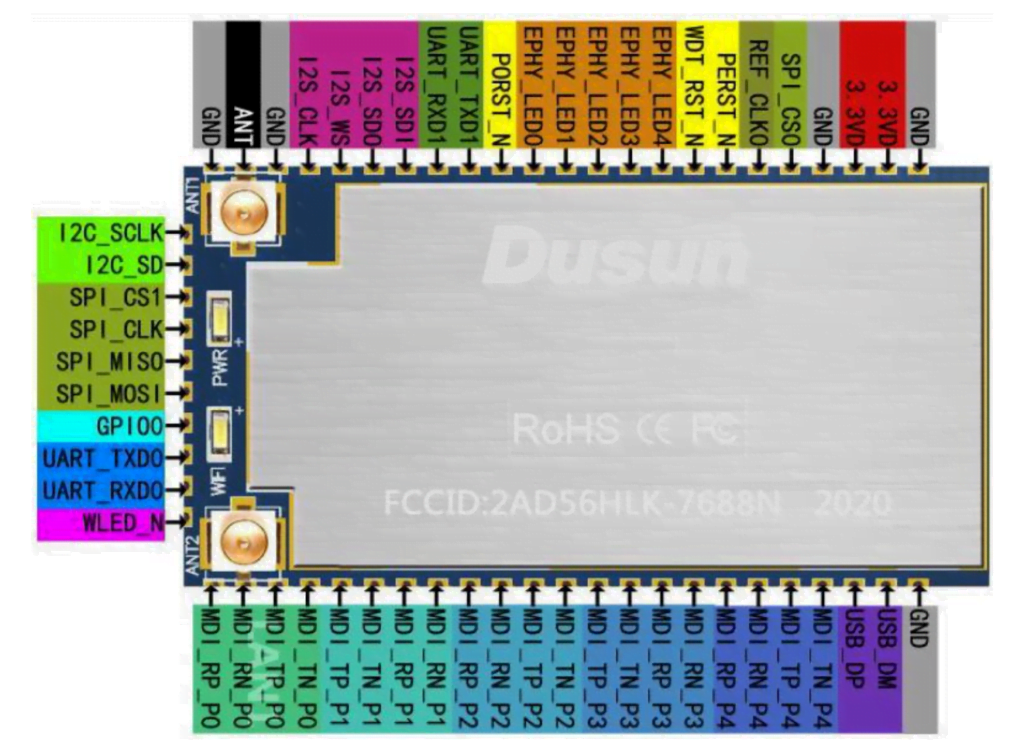
Top Side Coreboard
| Pin | Name | I/O Typ e | I/O Voltage (Unit: V) | Function | Remark |
|---|---|---|---|---|---|
| 1 | GND | P | Ground | System Power | |
| 2 | 3.3VD | P | Power,supplycurrent≥ 1000mA | ||
| 3 | 3.3VD | P | |||
| 4 | GND | P | Ground | ||
| 5 | SPI_CS0 | O | 3.3 | SPI0 chip select 0 | |
| 6 | REF_CLK0 | I/O | Reference clock output | ||
| 7 | PERST_N | I/O | 3.3 | PCIE device reset | Internal pull-up, Don't pull down |
| 8 | WDT_RST_N | I/O | 3.3 | Watchdog timeout reset | Pull down 1s to enter the AirKiss function of WeChat; Pull down 3s, Exits transparent transmission and enters AT mode; Pull down 6s, and the module will restore the default settings; |
| 9 | EPHY_LED4 | I/O | 3.3 | PORT4 LED, Active low |
LAN4 LED |
| 10 | EPHY_LED3 | I/O | 3.3 | PORT3 LED,Active low | LAN3 LED |
| 11 | EPHY_LED2 | I/O | 3.3 | PORT2 LED,Active low | LAN2 LED |
| 12 | EPHY_LED1 | I/O | 3.3 | PORT1 LED,Active low | LAN1 LED |
| 13 | EPHY_LED0 | I/O | 3.3 | PORT0 LED,Active low | WAN LED |
| 14 | PORST_N | I/O | 3.3 | CPU reset,Active low | CPU Reset,Floating |
| 15 | UART_TXD1 | O | 3.3 | Uart1 TXD | Uart1 TXD, if not use, Floating,Internal pull-up, Don't pull |
| 16 | UART_RXD1 | I | 3.3 | Uart1 RXD | Uart1 RXD,if not use, Floating |
| 17 | I2S_SDI | I/O | 3.3 | I2S data input | GPIO Optional |
| 18 | I2S_SDO | I/O | 3.3 | I2S data output | GPIO Optional, Internal pull-down, Don't pull up |
| 19 | I2S_WS | I/O | 3.3 | I2S Channel selection , 0:Left;1:Right |
GPIO Optional |
| 20 | I2S_CLK | I/O | 3.3 | I2S clock | GPIO Optional |
| 21 | GND | P | Ground | Ground | |
| 22 | ANT | P | Antenna, the default open | If you need to connect this pin, you need to remove the antenna base and replace it with a 0 ohm resistor |
|
| 23 | GND | P | Ground | Ground | |
| 24 | I2C_SCLK | I/O | 3.3 | I2C Clock | GPIO Optional |
| 25 | I2C_SD | I/O | 3.3 | I2C data | GPIO Optional |
| 26 | SPI_CS1 | I/O | 3.3 | SPI chip select 1 | Internal pull-down, Don't pull up |
| 27 | SPI_CLK | I/O | 3.3 | SPI clock | Internal pull-up, Don't pull down |
| 28 | SPI_MISO | I/O | 3.3 | SPI Bus data master in and slave out |
|
| 29 | SPI_MOSI | I/O | 3.3 | SPI Bus data master out and slave in |
|
| 30 | GPIO0 | I/O | 3.3 | Universal input and output interface |
|
| 31 | UART_TXD0 | O | 3.3 | Uart0 TXD | Uart0 TXD, if not use, Floating, Internal pull-down, Don't pull up |
| 32 | UART_RXD0 | I | 3.3 | Uart0 RXD | Uart0 RXD, if not used, Floating |
| 33 | WLED_N | I/O | 3.3 | Wi-Fi LED, Active low | During Wi-Fi communication, the WI-FI LED flashes and can be Floating |
| 34 | MDI_RP_P0 | I/O | PORT0 Network signal is receiving positive |
WAN port, if not used, Floating | |
| 35 | MDI_RN_P0 | I/O | PORT0 Network signal is receiving negative |
||
| 36 | MDI_TP_P0 | I/O | PORT0 Network signal is sending positive |
||
| 37 | MDI_TN_P0 | I/O | PORT0 Network signal is sending negative |
||
| 38 | MDI_TP_P1 | I/O | PORT1 Network signal is receiving positive |
LAN Port1, if not used, Floating | |
| 39 | MDI_TN_P1 | I/O | PORT1 Network signal is receiving negative |
||
| 40 | MDI_RP_P1 | I/O | PORT1 Network signal is sending positive |
||
| 41 | MDI_RN_P1 | I/O | PORT1 Network signal is sending negative |
||
| 42 | MDI_RP_P2 | I/O | PORT2 Network signal is receiving positive |
LAN Port2, if not used, Floating | |
| 43 | MDI_RN_P2 | I/O | PORT2 Network signal is receiving negative |
||
| 44 | MDI_TP_P2 | I/O | PORT2 Network signal is sending positive |
||
| 45 | MDI_TN_P2 | I/O | PORT2 Network signal is sending negative |
||
| 46 | MDI_TP_P3 | I/O | PORT3 Network signal is receiving positive |
LAN Port2, if not used, Floating | |
| 47 | MDI_TN_P3 | I/O | PORT3 Network signal is receiving negative |
||
| 48 | MDI_RP_P3 | I/O | PORT3 Network signal is sending positive |
||
| 49 | MDI_RN_P3 | I/O | PORT3 Network signal is sending negative |
||
| 50 | MDI_RP_P4 | I/O | PORT4 Network signal is receiving positive |
LAN Port4, if not used, Floating | |
| 51 | MDI_RN_P4 | I/O | PORT4 Network signal is receiving negative |
||
| 52 | MDI_TP_P4 | I/O | PORT4 Network signal is sending positive |
|
|
| 53 | MDI_TN_P4 | I/O | PORT4 Network signal is sending negative |
||
| 54 | USB_DP | I/O | USB data positive | If not used, Floating | |
| 55 | USB_DM | I/O | USB data negative | If not used, Floating | |
| 56 | GND | P | Ground | Ground |
Remark:
I-input; O-output; I/O-digital I/O; P-power supply. The drive current of the IO ports is 4mA, and the voltage level of all IO pins is 3.3V.
The red color in the name column indicates that it is related to the chip’s startup, and it cannot be pulled up or down from the outside nor connected to the drive source.
5 Electrical Parameters of DSOM-080M MediaTek MT7628 SOM
| Parameter | Description | Min | Typ | Max | Unit |
|---|---|---|---|---|---|
| Ts | Storage temperature |
-40 | - | 85 | ℃ |
| Ta | Operating temperature |
-20 | - | 55 | ℃ |
| 3.3VD | Input voltage | -0.3 | - | 3.8 | V |
| Electrostatic discharge voltage (human body model) | TAMB-25℃ | - | - | 2 | KV |
| Electrostatic discharge voltage (machine model) | TAMB-25℃ | - | - | 0.5 | KV |
Note: Exposure to conditions beyond the absolute maximum ratings may cause
permanent damage and affect the reliability and safety of the device and its systems.
The functional operations cannot be guaranteed beyond specified values in the
recommended conditions.
| Parameter | Description | Min | Typ | Max | Unit | ||||
|---|---|---|---|---|---|---|---|---|---|
| Ta | Operating temperature | -10 | 25 | 55 | °C | ||||
| 3.3VD | 3.0 | 3.3 | 3.6 | V | |||||
| VIL | Low-level input voltage | -0.3 | - | VDD*0.25 | V | ||||
| VIH | High-level input voltage | VDD*0.75 | - | 3.6 | V | ||||
| VOL | Low-level output voltage | - | VDD*0.1 | V | |||||
| VOH | High-level output voltage | VDD*0.8 | - | - | V | ||||
| ISTD | No-load running current | 130 | 230 | mA | |||||
| Ipeak | Peak current | - | 850 | - | mA | ||||
| PAVG | Average power | - | 650 | - | mW | ||||
| Fo | Operating frequency | 2412 | 2484 | Mhz | |||||
6 Hardware Design Guidelines of DSOM-080M MediaTek MT7628 SOM
The MT7628AN chip features an SPI controller with a choice of CS0 and CS1, which can be utilized for connecting SPI devices. The recommended design for the SPI interface, including drop-down and match, is shown in the following table
| Name | Internal State | External connection mode | Description (chip side) | |||||
|---|---|---|---|---|---|---|---|---|
| SPI_MOSI | Pull-Down | Direct connection | SPI Master output | |||||
| SPI_MISO | \ | Direct connection | SPI Master input | |||||
| SPI_CLK | Pull-Up | 33ohm resistor in series | SPI clock | |||||
| SPI_CS1 | Pull-Down | Direct connection | SPI chip select1 | |||||
| SPI_CS0 | \ | Direct connection | SPI chip select0,Has been used for internal flash chips |
|||||
| Name | Internal State | External connection mode | Description (chip side) | ||||||
|---|---|---|---|---|---|---|---|---|---|
| I2C_SCLK | \ | 33ohm resistor in series, 4.7K resistance pull up |
I2C Clock | ||||||
| I2C_SD | \ | 33ohm resistor in series, 4.7K resistance pull up |
I2C Data | ||||||
The DSOM-080M module has a set of USB 2.0 interfaces as the host. Please note the following in the design:
- Ensure that the internal capacitance of the ESD device is less than 3PF when the USB/DP is close to the access port.
- To restrain electromagnetic radiation, reserve the common-mode inductor on the signal line, and choose to use resistance or common-mode inductor according to the actual situation in the debugging process.
The design recommendations for the USB 2.0 interface are shown in the following table:
| Name | External Connection Mode | Description | |||||
|---|---|---|---|---|---|---|---|
| USB_DP | 2.2ohm resistor in series | USB data is positive | |||||
| USB_DN | 2.2ohm resistor in series | USB data is negative | |||||
USB 2.0 Signal Design Rules:
- The internal offset of the difference pair should be less than 2 PS;
- The length of the difference pair should be less than 3 inches;
- The differential convection layer should have less than 3 holes.
- The differential pair impedance should be controlled at 90 ohms +/-10%.
- The distance between the differential pair and other signals should follow the 3W principle
| Name | External Connection Model | Description | ||||||
|---|---|---|---|---|---|---|---|---|
| I2S_SDI | 22ohm resistor in series | I2S data input terminal | ||||||
| I2S_SDO | 22ohm resistor in series | I2S data output terminal | ||||||
| I2S_WS | 22ohm resistor in series | I2s channel selection, 0: left; 1: Right | ||||||
| I2S_CLK | 22ohm resistor in series | I2S clock | ||||||
The DSOM-080 module supports a total of 1 WAN and 4 LANs. LANs can be used as other functions when not needed. However, note that all four LANs can only be used either as LANs or as other GPIO-like functions. There is no case where LAN Port 1 is used as a LAN, and LAN Port 2/3/4 is used as other GPIO-like functions.
Please Note the following during design:
Near the Ethernet port, differential mode and common mode protection devices should be added, as shown in the following figure

7 Product Dimensions of DSOM-080M MediaTek MT7628 SOM

Module Dimensions

Suggested Package Dimensions
| Item | Parameter |
|---|---|
| Core Board Size | 18.7 mm x 35.2mm x 2.8mm |
| Pin Spacing | 1.4mm |
| Warpage | less than 0.5 % |
8 Production Guide of DSOM-080M MediaTek MT7628 SOM
Select modules that can be SMT or in-line packaged according to the customer’s PCB design scheme. If the board is designed for SMT packaging, use SMT-packaged modules. If the board is designed for in-line assembly, use in-line assembly.
Modules must be soldered within 24 hours of unpacking. If not, place them in a dry cabinet with a relative humidity of no more than 10% or re-pack them in a vacuum and record the exposure time (total exposure time must not exceed 168 hours).
Instruments or equipment required for SMT assembly:
- SMT Mounter
- SPI
- Reflow soldering
- Oven temperature tester
- AOI
Instruments or equipment required for baking:
- Cabinet ovens
- Antistatic high-temperature trays
- Antistatic and high-temperature gloves
Moisture-proof bags must be stored at a temperature <40°C and humidity <90% RH. Dry-packed products have a shelf life of 12 months from the date of sealing of the package. Sealed packaging with humidity indicator card.

The vacuum bag is found to be broken before unpacking.
After unpacking, the bag is found to be without a humidity indicator card.
The humidity indicator card reads 10% or more after unpacking, and the color ring turns pink.
Total exposure time after unpacking exceeds 168 hours.
More than 12 months from the date of the first sealed packaging.
Baking parameters are as follows:
Baking temperature: 60°C for reel packs, humidity less than or equal to 5% RH; 125°C for tray packs, humidity less than or equal to 5% RH (high-temperature-resistant trays, not blister packs for tow trays).
Baking time: 48 hours for reel packaging; 12 hours for pallet packaging.
Alarm temperature setting: 65°C for reel packs; 135°C for pallet packs.
After cooling to below 36°C under natural conditions, production can be carried out.
If the exposure time after baking is greater than 168 hours and not used up, bake again.
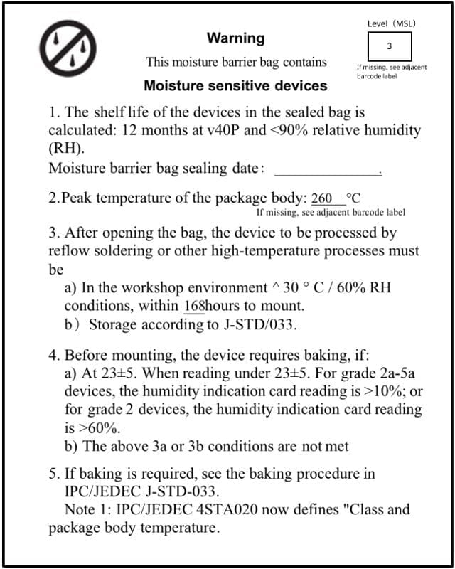
If the exposure time is more than 168 hours without baking, it is not recommended to use the reflow soldering process to solder this batch of modules. The modules are class 3 moisture-sensitive devices and may become damp when the exposure time is exceeded. This may lead to device failure or poor soldering when high-temperature soldering is carried out.
Please protect the module from electrostatic discharge (ESD) during the entire production process.
To ensure product qualification rates, it is recommended to use SPI and AOI test equipment to monitor solder paste printing and placement quality.
Please follow the reflow profile for SMT placement with a peak temperature of 245°C. The reflow temperature profile is shown below using the SAC305 alloy solder paste as an example.
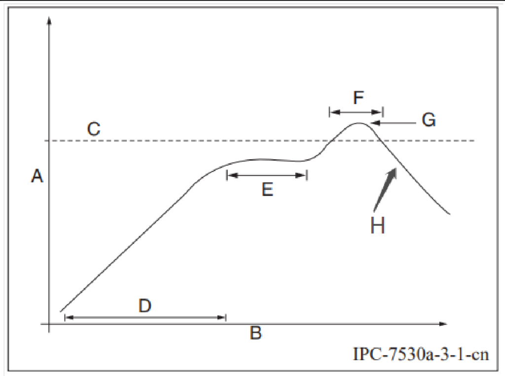
Description for graphs of curves.
A: Temperature axis
B: Time axis
C: Alloy liquid phase line temperature: 217-220°C
D: Slope of temperature rise: 1-3°C/s
E: Constant temperature time: 60-120s, constant temperature: 150-200°C
F: Time above liquid phase line: 50-70s
G: Peak temperature: 235-245°C
H: the slope of temperature reduction: 1-4°C/s
Note: The above-recommended curves are based on SAC305 alloy solder paste as an example. Please set the recommended oven temperature curve for other alloy solder pastes according to the solder paste specification.
| Model | DDR | Flash |
|---|---|---|
| DSOM-080M-Z | 64Mb | 32Mb |
| DSOM-080M-C | 128Mb | 32Mb |
9 Appendix of DSOM-080M MediaTek MT7628 SOM
Extendable the Reuseable Function Menu
| PIN | Name (function1) | Function 2 | Function 3 | Function 4 | GPIO# |
|---|---|---|---|---|---|
| 1 | GND | ||||
| 2 | 3.3VD | ||||
| 3 | 3.3VD | ||||
| 4 | GND | ||||
| 5 | SPI_CS0 | GPIO#10 | |||
| 6 | REF_CLK0 | GPIO#37 | |||
| 7 | PERST_N | GPIO#36 | |||
| 8 | WDT_RST_N | GPIO#38 | |||
| 9 | EPHY_LED4 | JTAG_RST_N | GPIO#39 | ||
| 10 | EPHY_LED3 | JTAG_CLK | GPIO#40 | ||
| 11 | EPHY_LED2 | JTAG_TMS | GPIO#41 | ||
| 12 | EPHY_LED1 | JTAG_TDI | GPIO#42 | ||
| 13 | EPHY_LED0 | JTAG_TDO | GPIO#43 | ||
| 14 | PORST_N | ||||
| 15 | UART_TXD1 | PWM_CH0 | GPIO#45 | ||
| 16 | UART_RXD1 | PWM_CH1 | GPIO#46 | ||
| 17 | I2S_SDI | PCMDRX | GPIO#0 | ||
| 18 | I2S_SDO | PCMDTX | GPIO#1 | ||
| 19 | I2S_WS | PCMCLK | GPIO#2 | ||
| 20 | I2S_CLK | PCMFS | GPIO#3 | ||
| 21 | GND | ||||
| 22 | ANT | ||||
| 23 | GND | ||||
| 24 | I2C_SCLK | GPIO#4 | |||
| 25 | I2C_SD | GPIO#5 | |||
| 26 | SPI_CS1 | GPIO#6 | |||
| 27 | SPI_CLK | GPIO#7 | |||
| 28 | SPI_MISO | GPIO#9 | |||
| 29 | SPI_MOSI | GPIO#8 | |||
| 30 | GPIO0 | GPIO#11 | |||
| 31 | UART_TXD0 | GPIO#12 | |||
| 32 | UART_RXD0 | GPIO#13 | |||
| 33 | WLED_N | GPIO#44 | |||
| 34 | MDI_RP_P0 | ||||
| 35 | MDI_RN_PO | ||||
| 36 | MDI_TP_P0 | ||||
| 37 | MDI_TN_P0 | ||||
Documentations
DusunIoT offers full set of development resources including QUICK START, SDK, Firmware packaging, module firmware, Tools, vairous third party software,etc.


