In the dynamic realm of the Internet of Things (IoT), IoT gateways have emerged as frontrunners in providing efficient, reliable, and low-power wireless communication solutions. This has propelled them to the forefront, particularly in smart home IoT applications. This comprehensive guide delves into the intricate customization development process of smart Zigbee gateways, placing a keen focus on their core testing procedures and critical technical metrics. These encompass sensitivity, transmission power, and EVM performance, among others. To further illuminate these concepts, we’ll examine the testing practices employed by Dusun’s Zigbee gateways.
Grasping the intricacies of Zigbee gateway testing is paramount, as these tests serve as gatekeepers, ensuring the performance, reliability, and adherence to standards of IoT gateway devices before they embark on their real-world journeys. This is crucial for guaranteeing that zigbee gateways operate seamlessly in varied environments and interact effortlessly with other Zigbee devices.
This guide is meticulously crafted to equip readers with a comprehensive perspective, bridging the gap between theory and practice. It empowers developers and technical experts to fully comprehend and master advanced testing methods for Zigbee gateways. Whether your endeavor lies in optimizing existing products or venturing into the realm of innovative IoT solutions, this article will serve as an invaluable resource.
Zigbee RF Test and Analysis (Laboratory Test Parameters)
Zigbee testing specifications are primarily anchored in the IEEE 802.15.4 standard, which meticulously evaluates overall device performance. This encompasses both transmitter and receiver performance testing. Transmitter RF requirements are meticulously divided into two facets: ensuring the quality of the transmitted signal within the designated channel and effectively preventing frequency components from unwanted transmissions. The receiver, on the other hand, must possess the fortitude to withstand a wide spectrum of interference signals, ensuring reliable demodulation of the useful signal while precluding excessive transmission sensitivity.
Transmitter Testing
To unravel the intricacies of the transmitted signal from a transmitter, an ideal receiver is employed to convert it into a digital baseband signal. Signal processing is then meticulously performed in the digital domain to extract the corresponding metrics. In actual testing scenarios, high-performance spectrum analyzers or signal analyzers typically assume the role of the ideal receiver. After traversing the ideal receiver and undergoing AD conversion, the IO data is obtained. This data is then subjected to a series of pulse shaping filtering, interpolation, and decimation steps to yield the initial measurement signal. Subsequently, the measurement signal undergoes corrections for amplitude, phase, frequency, and time, culminating in the corrected measurement signal. Finally, demodulation, de-expansion, demodulation, remodulation, re-expansion, and re-jamming are applied to the measurement signal. Shaping filtering is then employed to obtain the reference signal. The channel-measured metrics are ultimately derived by comparing and calculating the corrected measurement signal and the reference signal.
The transmitter test metrics encompass the following crucial test items:
- Transmitter Signal Output Power:
Transmitter power must not interfere with other devices and systems; therefore, Zigbee output power must adhere to the specified requirements. The maximum transmission power in different regions varies across the corresponding frequency bands.
- Spectral Emission Mask
For wireless data communication Zigbee, the spectral emission mask and spurious emission characteristics of the transmitter directly influence its potential interference with existing radio services. The transmitter spectrum power must remain below the specified limits. For relative and absolute limits, the average power spectrum mean measurement employs a resolution bandwidth of 100kHz. For relative limits, the reference power is the highest average power spectrum density at the center frequency fc±600kHz.
- Center Frequency Tolerance
The transmitter center frequency tolerance must fall within ±40ppm of the maximum frequency value. Currently, Dusun IoT company exit center frequency error requirement is <±30kHz, better than the standard design.
- Error Vector Magnitude (EVM)
EVM stands for Error Vector Magnitude, and it encapsulates the error vector (encompassing amplitude and phase offset) that characterizes the vector difference between the ideal error-free reference signal (physical layer specification reference signal) and the actual transmitted signal at a given moment. By delving into the EVM parameter, we can gain insights into the amplitude error and phase error of an output signal.
: Zigbee Gateway Testing 1")
EVM serves as a crucial metric for evaluating the overall modulation quality of an RF system. It is defined as the error between the measured signal and the ideal signal on the signal constellation diagram. This parameter is influenced by various factors, including the transmitter’s modulation accuracy, the performance of the modulator, demodulator, power amplifier (PA), mixer, and transceiver.
For Zigbee transmitters, the EVM requirement is typically less than 35% when measuring 1000 symbols. The actual received signal should be measured on the baseband IQ symbols after the receiver system has recovered.
Transmitter Testing Practical
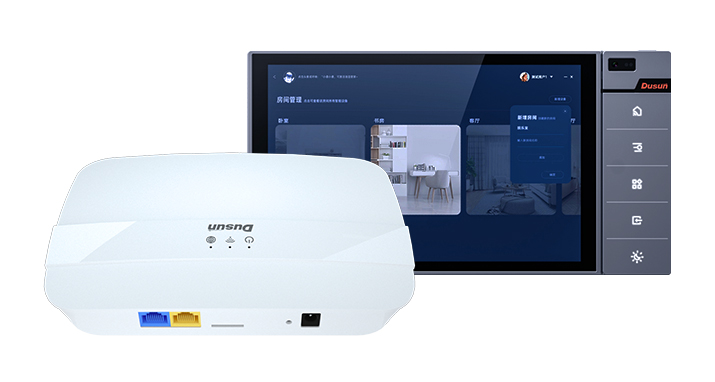
To illuminate the intricacies of transmitter testing, let’s delve into an example of Zigbee performance testing for a DSGW-520 smart home screen gateway (the latest product but not published now):
Zigbee Chip: EFR32MG21A020F768IM32-B
Zigbee Performance Parameters:
: Zigbee Gateway Testing 2")
Test Method:
- Connect the gateway’s Zigbee module to the LITEPOINT IQxstream-5G wireless analyzer using an ipex-to-SMA cable.
- Power on the gateway and enter the system. Issue a modulation wave command to test the three low, medium, and high channels (11, 18, and 26).
- Observe the transmitted power, frequency offset, and EVM parameters on the wireless analyzer interface and verify that they fall within the specified range.
Test Results:
: Zigbee Gateway Testing 3")
: Zigbee Gateway Testing 4")
Receiver Testing
The objective of receiver testing is to meticulously evaluate whether the overall performance of the receiver portion of wireless data communication adheres to the design and acceptance requirements. In general, the test port is located at the RF input port. A standard signal source is employed to generate RF test signals, which are then fed into the receiver. The output bitstream is subsequently analyzed to assess the receiver’s performance.
Receiver testing encompasses a range of crucial test items, including:
- Receiver Sensitivity:
Receiver sensitivity is defined as the minimum input power required to achieve a specified packet error rate under specified conditions.
| Term | Definition | Conditions |
| Packet Error Rate (PER) | Average probability of receiving a transmission packet error | Random measurement of PSDU |
| Receiver Sensitivity | Minimum input threshold of the receiver at a given PER | PSDU Length=20 bytes PER<1% Power is measured at the antenna terminal |
Receiver Testing Practical
The following is a Zigbee performance test of a DSGW-520 Smart Gateway;
Zigbee chip: EFR32MG21A020F768IM32-B
Zigbee performance parameters:
: Zigbee Gateway Testing 5")
Test method:
- 1) LITEPOINT IQxstream-5G wireless comprehensive tester connects the gateway Zigbee module through the ipex to SMA cable
- 2) The gateway is powered on to enter the system, and the Zigbee module is adjusted to enter the receiving mode.
- 3) The wireless comprehensive tester interface loads the transmission waveform file, sets the three channels of 11, 18, and 26 respectively, sends waveform data, checks the number of waveform data received by the gateway, and counts the success rate.
Test results:
: Zigbee Gateway Testing 6")
Zigbee Gateway Communication Distance Test (Actual Test)
This following describes an example of a Zigbee gateway communication distance test using the DSW-210 Edge Computing Gateway (Zigbee supported) as an example.
Test Principle
Connect the product to the gateway in an open outdoor area.Gradually increase the distance between the product and the gateway. Evaluate the maximum communication distance based on the data reporting success rate.
Zigbee Gateway Placement
Place the gateway in the following four directions. Place the device to be tested on a stand at a height of about 1.5 meters.Compare test data for each direction.
: Zigbee Gateway Testing 7")
Sub-Device Placement
The following figure shows an example of a door/window sensor.
: Zigbee Gateway Testing 8")
Maximum Communication Distance Test Method
- Power on the product and place it in the required direction according to the product placement requirements, maintaining a distance of about 1.5 meters from the ground.
- Use the test App to add the Zigbee gateway and pair the sub-device with the Zigbee gateway successfully.
- Slowly increase the distance between the product and the gateway and observe the data changes.
- When moving, the communication between the product and the gateway will be affected to a certain extent. It is necessary to continuously observe the control status of the product on the mobile phone App.
Judging the Maximum Communication Distance
When the App control product is stuck or cannot control the product, stop and observe.
If the App control is restored within 2 minutes, continue to increase the distance.
If the App cannot control the product for more than 2 minutes, the position is considered to be the maximum communication distance.
Change the product placement direction and repeat the above test to determine the maximum communication distance.
Zigbee Gateway Stability Test
Environmental Setup
- Simulate user environment, which can be performed in a home laboratory.
- Mount the maximum number of 128 Zigbee sub-devices on the gateway and run the gateway stably for 7*24 hours.
Test Steps
- Mount the maximum number of Zigbee sub-devices specified in the specification and test for a long time for 7 days * 24 hours.
- Scene mode:
Mode 1: Low-frequency single control: Select 1 device according to sku, control 1 device every 1 minute (all functions, list required), control 10 times continuously, and traverse all skus. Select different devices in different rounds. 9 skus, takes about 90 minutes.
Mode 2: Low-frequency multi-control: Control all devices, turn ON every 1 minute and turn OFF another 1 minute, control 10 rounds (ON+OFF) continuously, takes about 20 minutes. Set up multiple groups and adjust the lights (list required).
Mode 3: High-frequency single control: Control each device individually, immediately control the next instruction after completing an instruction (tentatively 10 seconds timeout), select 1 device according to sku. Select different devices in different rounds. (All functions, list required)
Mode 4: High-frequency multi-control: Send group (all devices ON/OFF) instructions every 3 seconds, send 11 times in succession, read the last status, and record whether it is successful. Set up multiple groups and adjust the lights (list required).
(1) Repeat the above 4 scene modes once as a group, and continuously loop.
(2) The large data volume test focuses on indicators such as gateway stability, sub-device online rate, control response delay, and execution success rate.
Test Standards
Online rate and scene execution success rate are monitored through the iottest platform. The monitoring environment is the online production environment, and the monitoring time is 7 days. The standards are reached: online rate 99%, scene execution success rate 99%; device control success rate 99%, control average time<3s.
Test Results
Automated test tool test interface
: Zigbee Gateway Testing 9")
| Test | Result | Details |
| Panel single control | PASS | * Success rate: 99% or above* Longest response time: 4.85s* Average time for 4 sets of data (rows 3, 9, 13, and 19) is above 0.2s, while the average time for the rest is below 0.17s. |
| Panel multi-control | PASS | * Success rate: 99% or above* |
| Lighting single control | PASS | * Row 56, high-frequency single control, data success rate is 99.9%. The rest are 100%.* Longest response time: 3.52s* Average time is around 0.2s. |
| Lighting multi-control | PASS | * Success rate: 99% or above* |
Zigbee Gateway Test Reports
RF Laboratory Performance Test Report
| Performance Testing | Test channel | 11 | 18 | 26 | Sensitivity Standard | Result |
| Center frequency MHz | 2405 | 2440 | 2480 | Sensitivity≤102.5dBm;PER≤1%TX power ≥18dBm;EVM≤15%;Frequency Deviation≤30 | PASS | |
| Power (dBm) | 19.42 | 19.66 | 19.83 | PASS | ||
| Frequency deviation (kHz) | -20.65 | -20.94 | -21.28 | PASS | ||
| EVM | 14.74% | 13.87% | 13.55 | PASS | ||
| Template | OK | OK | OK | PASS | ||
| Sensitivity | -103 | -103.5 | -103 | PASS |
Communication Distance Test Teport
| NO. | Open Distance Test | Direction | Test Times | Distance | Communication Success Rate | Test Results |
| 1 | 1. Open outdoor environment 2. The sub-device is at the farthest communication distance 3. Test the communication success rate reported by the sub-device at a fixed distance | 0° | 20 | 120m | 100% | Pass |
| 2 | 180° | 20 | 120m | 100% | Pass | |
| 3 | 90° | 20 | 120m | 100% | Pass | |
| 4 | —90° | 20 | 120m | 100% | Pass |
| NO. | Wall Penetration Test | Direction | Number of wall penetrations | Test standard | Can it be reported in real time | Test Results |
| 5 | 1. Indoor closed environment (inside a room) 2. Test whether the sub-device can report in real time after penetrating the wall | 0° | 1 | 3 | Yes | Pass |
| 2 | 3 | Yes | Pass | |||
| 3 | 3 | Yes | Pass | |||
| 6 | 180° | 1 | 3 | Yes | Pass | |
| 2 | 3 | Yes | Pass | |||
| 3 | 3 | Yes | Pass | |||
| 7 | 90° | 1 | 3 | Yes | Pass | |
| 2 | 3 | Yes | Pass | |||
| 3 | 3 | Yes | Pass | |||
| 8 | -90° | 1 | 3 | Yes | Pass | |
| 2 | 3 | Yes | Pass | |||
| 3 | 3 | Yes | Pass |
Function and Stability Test Report
| Items | Test Methods | Criteria | Test Results |
| Function and Stability Test Report | Environment setup: (1) Simulate the user environment, which can be performed in the home laboratory; (2) The gateway mounts a maximum of 128 Zigbee sub-devices, with normal data volume, and the gateway runs stably for 7*24 hours. Test steps: (1) Mount the maximum number of Zigbee sub-devices specified in the specification, and test for a long time for 7 days*24 hours; (2) Scenario mode: Mode 1 Low-frequency single control: Select 1 by sku, control 1 device every 1 minute (full function, need to be listed), control 10 times continuously, and traverse all sku. Select different devices for different rounds. 9 sku, it takes about 90 minutes. Mode 2 Low-frequency multi-control: Control all devices, control ON every 1 minute/control OFF every 1 minute, control 10 rounds continuously (ON+OFF), it takes about 20 minutes. Set up several groups and adjust the lights (need to be listed). Mode 3 High-frequency single control: control a single device each time, after controlling a command (temporarily set to have a timeout of 10 seconds), immediately control the next command, and select 1 by sku. Select different devices in different rounds. (Full function, to be listed) Mode 4 High-frequency multi-control: send a group (all devices ON/OFF) command every 3 seconds, send it 11 times in a row, read the status of the last time, and record whether it is successful. Set up several groups and adjust the lights (to be listed). (3) The above 4 scene modes are cycled once as 1 group, and they are cycled continuously (4) The large data volume test focuses on indicators such as gateway stability, sub-device online rate, control response delay, and execution success rate. | 1. The online rate and scene execution success rate are monitored through the iottest platform. The monitoring environment is the online production environment. The monitoring time is 1 month, and the standard is achieved: the online rate is 99%, and the scene execution success rate is 99% (the Chinese region needs to provide the Meiju account and login password for device configuration) 2. The control success rate and control time are not monitored for long-term operation. The equipment control success rate is 99%, and the average control time is <3s | PASS |
Summary
In this article, we have explained a series of test instructions and use cases taking Dusun Zigbee smart gateway as example, including sensitivity test, continuous operation test, and reliable test. I believe that after reading this article, engineers will have a deeper understanding of Zigbee gateway related tests and performance.
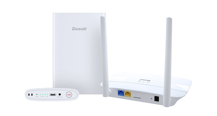
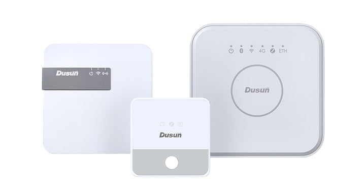
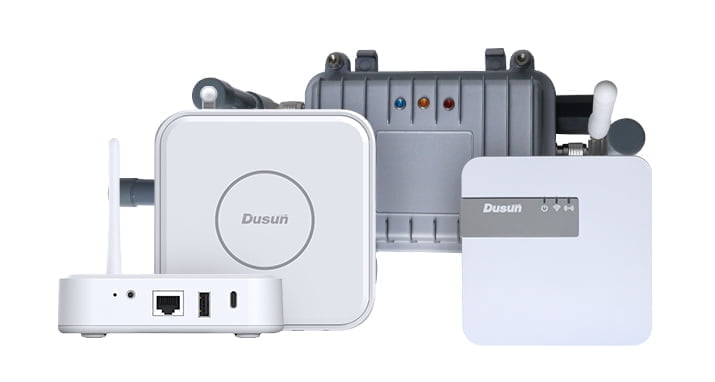
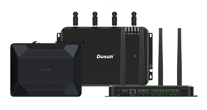
As a leading smart device solution provider, Dusun IoT provides a series of high-performance Zigbee gateway products and adopts strict testing procedures to verify and guarantee the functionality, stability and high performance of the equipment. These products not only support a wide range of automation applications, but also ensure ultra-high reliability and scalability. Dusun’s Zigbee gateway can provide seamless connection and ensure efficient communication between smart devices for various applications, including home automation, smart home, smart retail, smart building, etc.
Dusun IoT smart programmable Zigbee gateway is a hardware solution tailored for enterprise-level IoT developers. By providing a mature and complete hardware platform, customers can easily port or independently develop applications, or modify and secondary develop underlying firmware based on open source SDK, which greatly simplifies the complexity of enterprises in the development of IoT products and solutions, and helps customers achieve technological innovation and product implementation at a more efficient speed. Our powerful IoT product ODM service allows customers to customize gateway products according to specific needs, whether it is ID design or functional configuration, we can ensure that it fully meets your project needs.
Choose Dusun’s Zigbee gateway or ODM/OEM service, you will get industry-leading products and first-class technical services. Welcome to contact Dusun IoT at any time. We will wholeheartedly provide you with the most professional answers and services to help your products successfully lauch to market and create a better future together.